Tag Archives: Complex Profiles

A Simple Look at Complex Profiles

Profiles are a great way to add the level of detail you need in your model; obtaining complete control over the shape, surface and appearance of Walls, Columns, and Beams. But it is important to keep in mind the shape and reference origin of each of these tools.

Profiles applied to Walls and Beams may seem to be interchangeable; or a wall may seem like the better tool simply because it is called a “wall”, or because you need an opening in addition to the complex profile. But Walls and Beams behave very differently, especially when using profiles.

First, walls do not miter, they interlace and intersect at the corners. This is obvious, even when looking at a basic composite wall.

Things get even more cluttered at the intersection when you start to look at complex profiles, especially with curving and sloping faces. The examples below are completely fabricated, but emphasize the downside to using Complex Custom Profiles on walls.

If you look closely, you will see some odd irregularities and jutting projections where the above images are intersecting with another wall at their corners. By comparison, Beams intersect cleanly (as long as they are both flat, non-sloping, and at appropriate angles).

Now I am not saying that we should use Beams instead of Walls for all complex profiles, but being aware of how each tool is placed and reacts to their attributes (Building Materials, Surfaces, Composites, Profiles), how they interact with other elements, and how they affect file performance is critical in choosing the correct tool. I have seen at least one project that poor file performance was pin pointed to overly complex profiles applied to walls.

Slatted & Screened Walls

Todays post is inspired by some creative modeling by Maggie! Unfortunately her project was redesigned before I could get a screen shot of how she used a fence object to model slatted walls, but it got me thinking of other ways to model repetitious elements, other than dragging & managing multiple copies of columns, beams, etc.

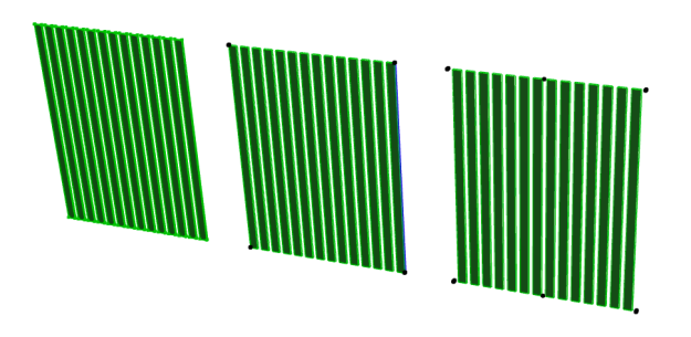
Screen Shot 2015-05-01 at 4.10.15 PMThe image above is of three slatted elements modeled with three separate tools. The left-most slats are morph elements boolean-ed into a single morph object. These have the advantage of easily extending both vertically and horizontally as a single element. The morph element can also be reoriented to a horizontal or even diagonal element with a single rotation. The profiles need to be simple and consistent or managing the element could be tedious and inaccurate.

The center slats are a complex profile with repeating shapes applied to a column. Advantages for this method are the ability to slope the column, change the shape, size & spacing of the boards with a quick redraft of the custom profile and easy extension of the height and width. The profiles can be more complex than the morph element.

The right-most slats are a fence object. This object has an advantage of being the easiest to change the element width, board spacing and size with no redrafting or manual object editing. Its disadvantages are that the boards must be oriented vertically or horizontally and can only be square or round profiles depending on the fence element used. The plan symbol for these objects can also be limited, which may be the most discouraging factor for this option.

All three options are a cleaner and more manageable solution to separate columns individually placed and coordinated.

Wall Intersection + Column + Custom Profile

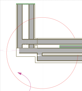
Sometimes no amount of building material priorities, wall junction priorities and creative composites will yield the plan view you are aiming for. For example, this is a wall relationship with cluttered cores and finish skins applied to 4 different composites:Screen Shot 2015-04-24 at 1.32.04 PMThis can quickly be cleaned up by creating a new custom profile. Copy the walls in the plan view and paste into the custom profile window. Delete all lines, crop to the minimum effective dimensions, consolidate fills, and adjust fill border pens to match the composites. Store the profile for future editing.

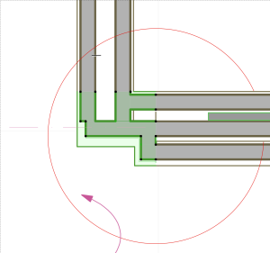
Screen Shot 2015-04-24 at 1.31.47 PMThe result is a clean plan symbol, which matches all building materials and surfaces already applied to the model:Screen Shot 2015-04-24 at 1.34.54 PM

Rotating Beams Without Stored Custom Profiles

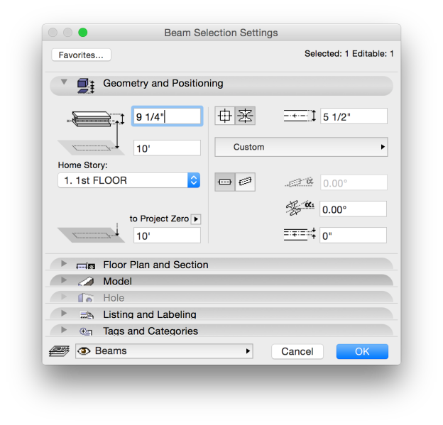
It is possible to have a beam rotated to a specific angle without the use of a stored custom profile! If the beam is a simple square shape, but at a 30º angle, you do not need to create a rotated complex profile. Just select the Structure: Complex Profile button and leave the profile selection as Custom. You can then set the rotation angle.Screen Shot 2015-04-13 at 3.39.07 PM

For a square beam, the pet palette options for a top/end node are limited to resizing or moving:
Screen Shot 2015-04-13 at 3.39.37 PM

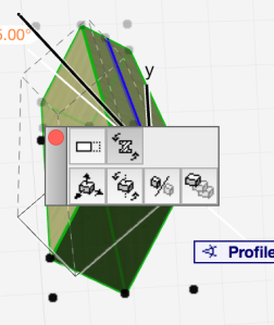
For a Custom Complex Profile beam the options are to stretch, rotate or move. Rotation can also be set using the pet palette in section view for precise matching to other sloped elements.Screen Shot 2015-04-13 at 3.39.57 PM

There are a few editing issues with this method; not all editing is obvious. Resizing can not be done in the model/section/plan views via the pet palette. To resize the beam open the selection settings and manually type the new size. Since custom profile building material and surface settings are stored in the profile manager you will not have the option to change these settings for a rotated beam. To apply a new surface or building material, switch the beam back to a square profile, make the building material/surface changes, and change back to a custom profile (the rotation, size and position will be retained from the previous setting).