Tag Archives: Tools

Arrow & Marquee Basics

The Arrow and Marquee tools seem simple enough, but there are some ways to use them to maximize efficiency.

Screen Shot 2019-02-19 at 2.22.26 PM.png

Arrow Tool Options


Screen Shot 2019-02-19 at 2.23.53 PM.png

Marquee Tool Settings

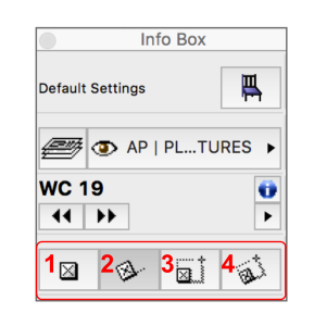
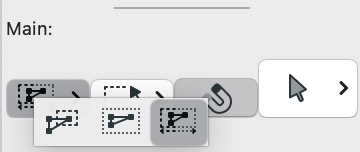
The basic Arrow Tool settings in the Info Box palette are:

  • Selection Method
  • Geometry Method
  • Quick Selection
  • Selection Type (for Morph Tool only)

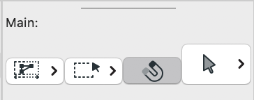
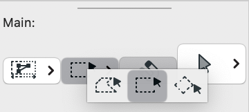
For the Marquee Tool, the Info Box includes:

  • Selection Method
  • Geometry Method

The Arrow Selection Method is similar to “Crossing Window” settings in AutoCAD, where direction of the click/drag/selection dictates what is included in a selection. Option 1 is to include all elements in the crossing window, Option 2 is to include only elements entirely within the crossing window, and Option 3 is to include all for Right to Left selections and only elements entirely in the window for Left to Right selections.

Screen Shot 2019-02-19 at 2.22.03 PM.png

Geometry method options are for rectangular selections, rotated rectangle, or polygon selections.

Screen Shot 2019-02-19 at 2.22.11 PM.png

The Quick Selection option is one that really boosts efficiency when mastered. Preferences on default settings vary; but I work with the Quick Selection option on. This feature determines wether clicking on the face or surface of an element selects the element or not. For example, you may want to start a drag selection by clicking inside a room and selecting all furniture in that room. To do this without selecting the slab, you need to have Quick Selection off. The shortcut for toggling this option on/off is to hold the Space bar down while initiating an arrow selection.

The fourth command on the arrow tool settings is the Selection Type. This feature can also be switched by default, but since it is a feature limited to the Morph tool, I recommend leaving it on the bold/gray (Normal) arrow by default. If you need to switch to the open/white (Sub Element) arrow, the shortcut for that is Control+Shift. This allows you to click on or select parts of a morph. Finding the right balance between all 4 arrow settings is key to working effectively with Morphs.

The Marquee is a bit simpler. The Selection method option is just a light or bold marquee. Those are for all visible elements on all stories, or just the current story (in plan view). These can be used for isolating parts of the model (F4: Show Selection/Marquee in 3d), stretching the model, selecting elements within a marquee, and more. The Geometry Method can be really useful for isolating portions of a model with specific limitations and shapes.

Advanced Object Placement

OK, that title may be a stretch. Placing an object is as simple as selecting it from the Object Tool Settings (the library folders), and clicking in the view it needs to be placed to. But there are some settings that can make placement a little more precise the first time, limiting or eliminating the need to rotate, move, or resize after placement.

First, you can define the insert point of the element. This is the point the element will be placed to when first dropped into the model.

Screen Shot 2016-07-19 at 12.53.28 PM

Insert Point Set to Rear Center of Object

Once the element settings are correct; for all attributes, size, elevation, information, layer, you can click ok to place the object. But there is one more step you can take to place the element multiple times ad different sizes and/or angles.

The Info Box Palette has a row of buttons that gives further control on how objects are placed.

Screen Shot 2016-07-19 at 12.54.12 PM

Object Geometry Method

Option 1 in the Info Box is a standard placement option that will place in the given rotation in the element settings.

Option 2 allows you to define a unique angle for each instance of the object being placed, when it is being placed.

Option 3 allows you to define a new X,Y dimension for the object graphically on the plan, based on the insertion point. This can work well for cabinet objects, tub, and shower objects or even furniture that needs to fit into a specific space.

Option 4 combines both options 1 and 2 into a three click placement to define rotation and size.

Go ahead and play around with these info box setting, and make sure you are aware of the insert point of the objects element settings before placing!


The Shell Tool for Objects

Building the Pendant Globe

The shell tool is one of the most underused tools in ARCHICAD. I use it for almost any shape revolved around an axis, but it can also be used in place of morph and mesh type elements. In the following example, I will show how Grace used the shell to build a light fixture, but it can also be used to model decorative columns, newels, pickets and other trim elements.

Screen Shot 2016-04-19 at 9.21.16 AM

In the above image, the globe for the pendant light is a shell, the “whishbone” hanger is a morph and the pendant is a scripted cylinder. To start, draft the shape of the fixture and split it in 1/2 since the shell is revolved around a center point.

Screen Shot 2016-04-19 at 9.22.23 AM

Next set up the shell tool to trace out & revolve around the drafted shape. Set the structure to basic and the geometry method to revolved. Set the building material, surface and all pens for saving to GDL.

Screen Shot 2016-04-19 at 10.09.35 AM

The shell will be “horizontal”, so it will need to be rotated. Click on the end/center node and use the slant axis option from the pet palette (second icon/top row). Normally rotation needs to be started in a 3d view and completed in floor plan view.

Screen Shot 2016-04-19 at 10.02.41 AM

Scripting the Pendant Hanger

After the globe and bracket are modeled and placed in the correct location relative to project 0,0,0 all that needs to be done is save to an object, then script in the pendant portion of the fixture. This was covered at the last AC East Bay usergroup, and you can find more info from that presentation here.

The scripting portion is actually very simple. Start by adding parameters to adjust the length & radius of the hanging cylinder and mounting base; the four parameters at the bottom of the image below.

Screen Shot 2016-04-19 at 10.22.18 AM

Next, you only need to script two cylinders that reference the parameter variables above. CYLIND is the script for a cylinder shape and it references the cylinder height then radius seperate by a comma. The mounting plate needs to be adjusted to the top of the first cylinder, so an ADDz command that references the first cylinder length is needed.

Screen Shot 2016-04-19 at 9.45.07 AM

I also added a hotspot so the to the 3d script to allow the object to be placed on the ceiling in 3d view.

Attribute & Element Relationships

I know this is a little bit of a fluff piece, but yesterday’s post on the difference between surfaces on a beam vs. morph got me thinking on ways that attributes relate to each other and how they relate to modeling & drafting elements.

Some attributes relate to other attributes. These attributes that collect attributes are sometimes referred to as “super attributes”. It may be surprising which attributes collect the most other attributes (spoiler, the winner is the custom profile!). Attributes primary function, however, is to define the appearance and geometry of the modeling and drafting elements. Some elements actually collect, use and reference other elements, such as the relationship between doors and windows and walls or skylights and roofs. Again, the modeling/drafting element which uses and compiles the most other elements (and attributes) may be surprising. This time its the Zone.

I apologize for the lack of clarity in the following diagram, but a traditional relationship chart started to look like a drunk spider weaving a web. Attribute naming & numbering is red, Elements are blue… Notice attributes never depend on elements, but may use other attributes to define their parameters:Screen Shot 2015-06-09 at 3.45.41 PM