First and most importantly it is essential to realize there are multiple parts to the grid tool and its interaction with the various drawings. The Grid Settings are relatively straight forward and simple to understand.
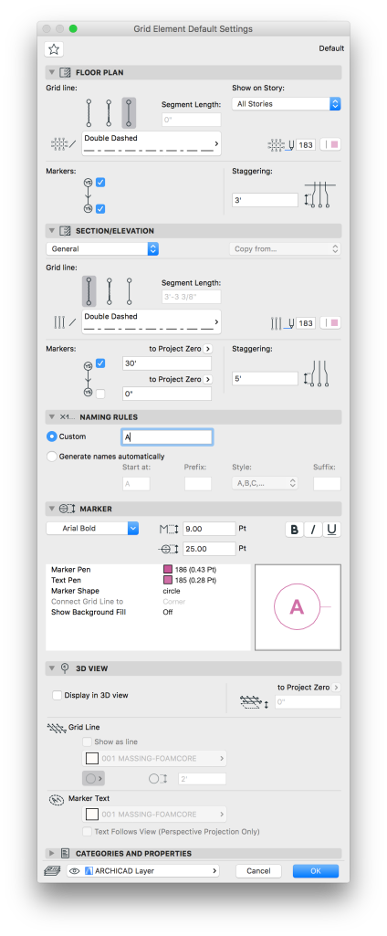
Standard Grid Settings from Template Favorites
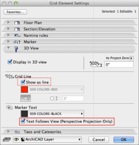
Above is an example of our default Grid Element Settings. If you find you do not have a Grid Element in your favorites, you can start with the line types and pen weights shown there. Also note the Naming Rules section; all grid elements have a custom name and are not generated automatically (this requires an automated grid placement that really only works for projects with very regular grids tied to beams and columns).
It is also important to note the upper right corner of the Grid Element Floor Plan Settings dialog. The drop down for Show on Story… allows you to define which stories each grid marker shows up on. I have audited projects in the past that used lines, circles, text, or even duplicate grid elements to selectively show grids on different stories. This drop down allows you to access a custom list of stories to show or hide each grid marker on. For most of our projects, this should be set to all stories for all grids, but if you need to customize this, there is an easy solution in the Grid Element Settings.
The Grid Tool Settings also have a section for Section/Elevation projections of the Grid. It is important to note that these settings DO NOT determine IF the grid will show up on Elevations or Sections, only HOW they will appear on those views.
To properly show Grids on an Elevation or Section, you need to set the Grid Settings in the views Marker Settings.

Elevation Selection Settings for Grid Appearance
To turn on Grids for an Elevation or Section simply go to the Grid Tool section of the Markers Selection Settings and check the box to Show Grid Elements. Make sure that the elevation settings do not have Auto-stagger selected. This feature can be useful, but more times than not it just messes with the opposite views appearance.
As an example, here is a quick mock up of an elevation with a grid offset:

Notice that Grid Element “C” is staggered over the top of Grid Element “B”. This is because the grid has been offset to the left of “B” on the opposite elevation. Staggering a grid element, either manually can cause this overlap. A manual adjustment applies the stagger to all elevation/section views that grid appears on. Automatic staggering should stagger grids appropriately for each view, but any manual changes will revert to the automatic position when the view is refreshed.
In the above example, Grid Element “C” may not need to appear on this elevation, since it is for a structural bearing line that does not relate to this side of the project. In the elevation or section marker settings, this Grid Element can easily be excluded from the Viewpoint of each marker individually. You simply need to go to the Marker Settings and click Selected under Show Grid Elements by Name and exclude the grids you do not want to show on that Viewpoint.

Elevation Settings to Show/Exclude Individual Grid Elements


