Tag Archives: Attributes

Dashed Marker Symbols

Archicad default Section, Elevation, and Interior Elevation markers do not have a control for “line type” parameters. As a result, many files end up with dashed lines within the marker head.

All attempts at reindexing, filling gaps in indexing, etc. have not fixed this. In some cases, reverting to the favorites or copying a marker from a working file, has resolved this; however, this has not always worked.

As an alternative work-around in a recent project experiencing this issue, I have added a Graphic Override rule to all GO view settings to change all marker element’s line types to Solid Line.

This results in marker line types showing solid for all views that this rule is applied to.

Avoid Library Pollution

We have gone through waves of library pollution, and it seems like one is washing over our projects again. So it’s time for a refresher on what this pollution is, the cause, how to avoid this pollution, and how to clean it up. It is important for all ARCHICAD users at WWA to read this post carefully to avoid this issue running through all our projects again.

What is the pollution and what causes it?

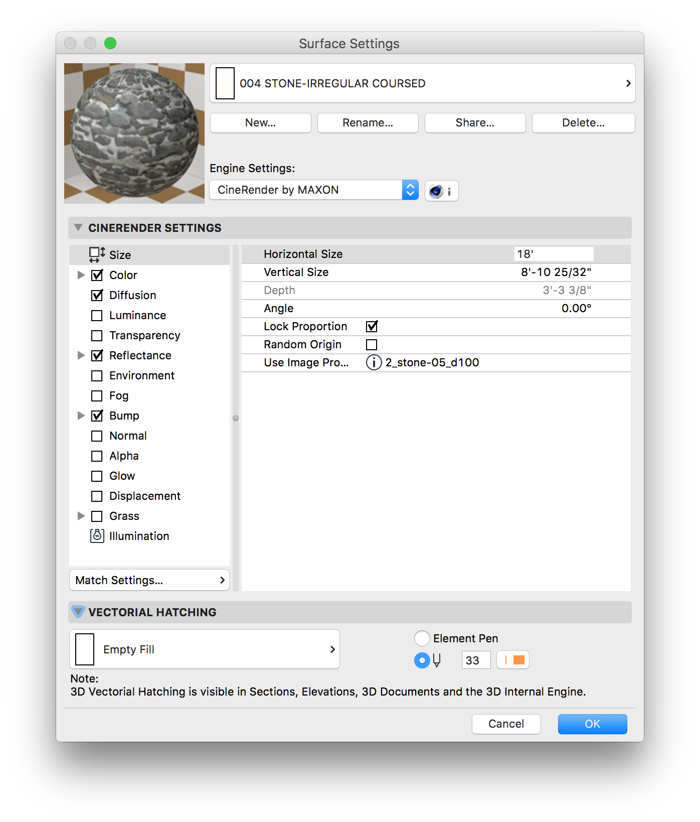
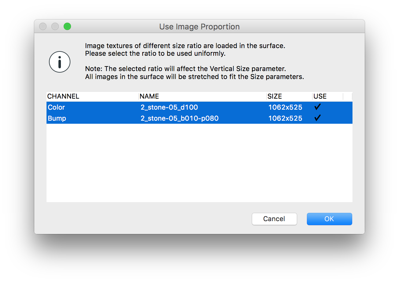
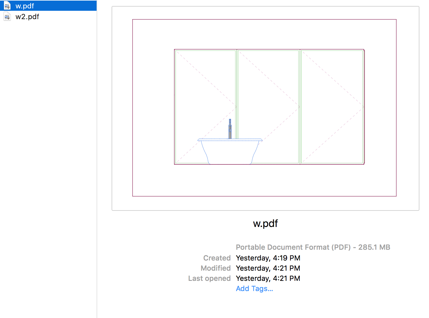
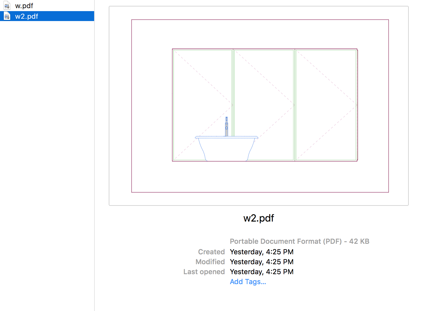
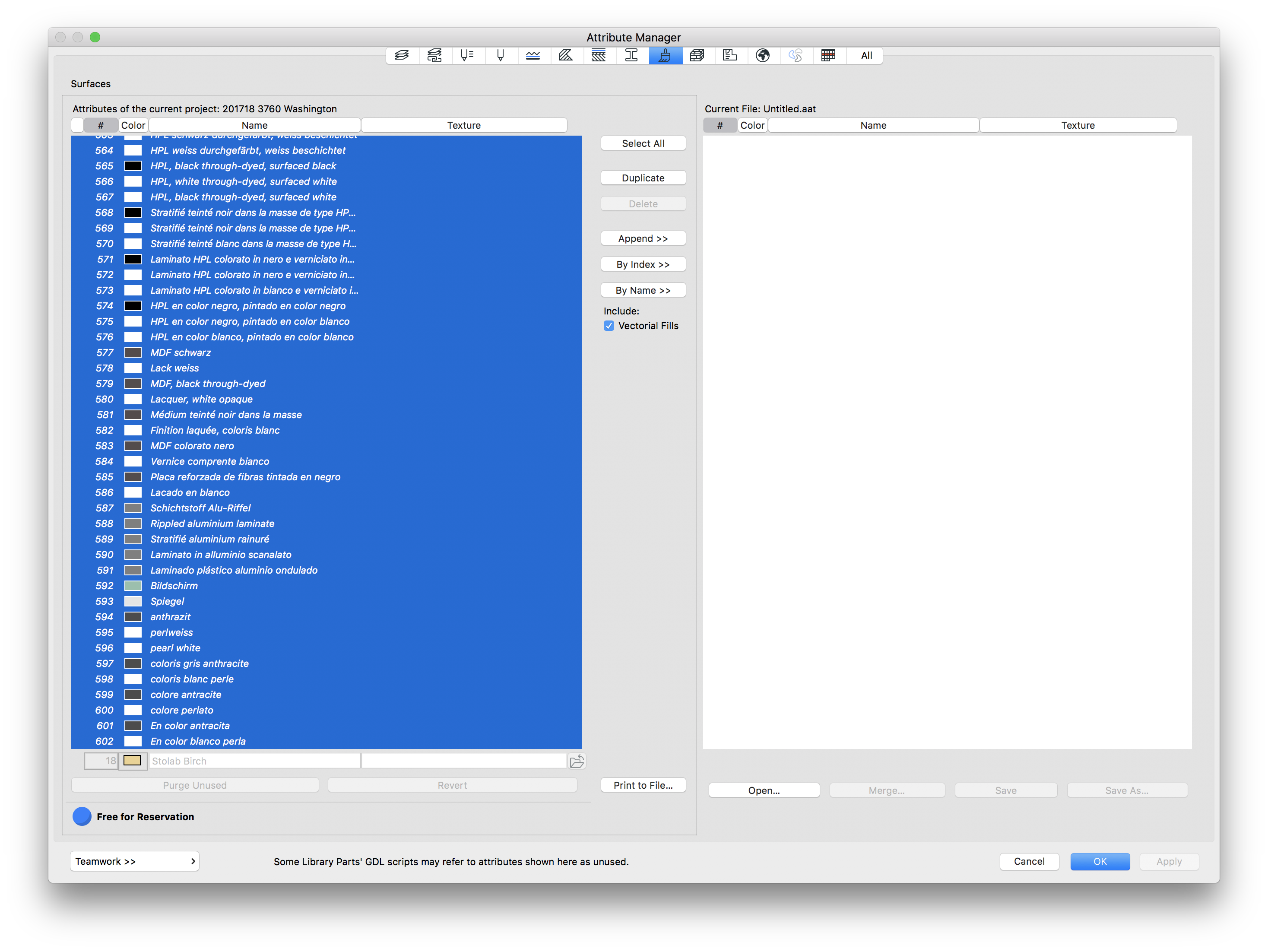
The pollution is a infiltration of unwanted attributes into a project. These attributes include Surfaces, Fills, and Line Types. The pollution is disruptive to our workflow because it pushes attributes out of sequence, creates massive gaps in attribute numbering, and gives us an annoyingly long list of attributes to dig through when working in ARCHICAD. As an example of the damage this issue can cause, here is a quick glance at some of the surfaces that came in from one instance of polluted library parts:

A-WWA Polluted.png

As you can imagine, sifting through that list of surfaces can be really annoying, even if it drops most of these surfaces at the end of the list. But as I mentioned, this also has an impact on fill types and line types.

So what is the trigger? It is caused by an infiltration of objects called Master_GDL.gdl into one or more of the libraries. Typically it is seen in the embedded library. This infiltration happens any time an infected file is copied from, and pasted into a clean file. So opening an old file and copying anything and pasting into your project will bring in these polluted attributes.

How can this pollution be avoided?

It is fairly simple to avoid the issue. If you need to bring anything in from another project, check the libraries and attributes first. If the file has any of the polluted surfaces (typically these are italicized and have names like Topas, Innivik, HAG, etc), do NOT copy from that file. You can either clean the file before copying from it (see below), or sandbox the content and clean it up before pasting, or redraw/model the content completely from scratch. It is important to note that no content is “safe” to copy/paste if the file is polluted. A single line/fill/text/label/wall/slab/etc copied out will drag the Master_GDL.gdl part with it.

How can the pollution be cleaned up?

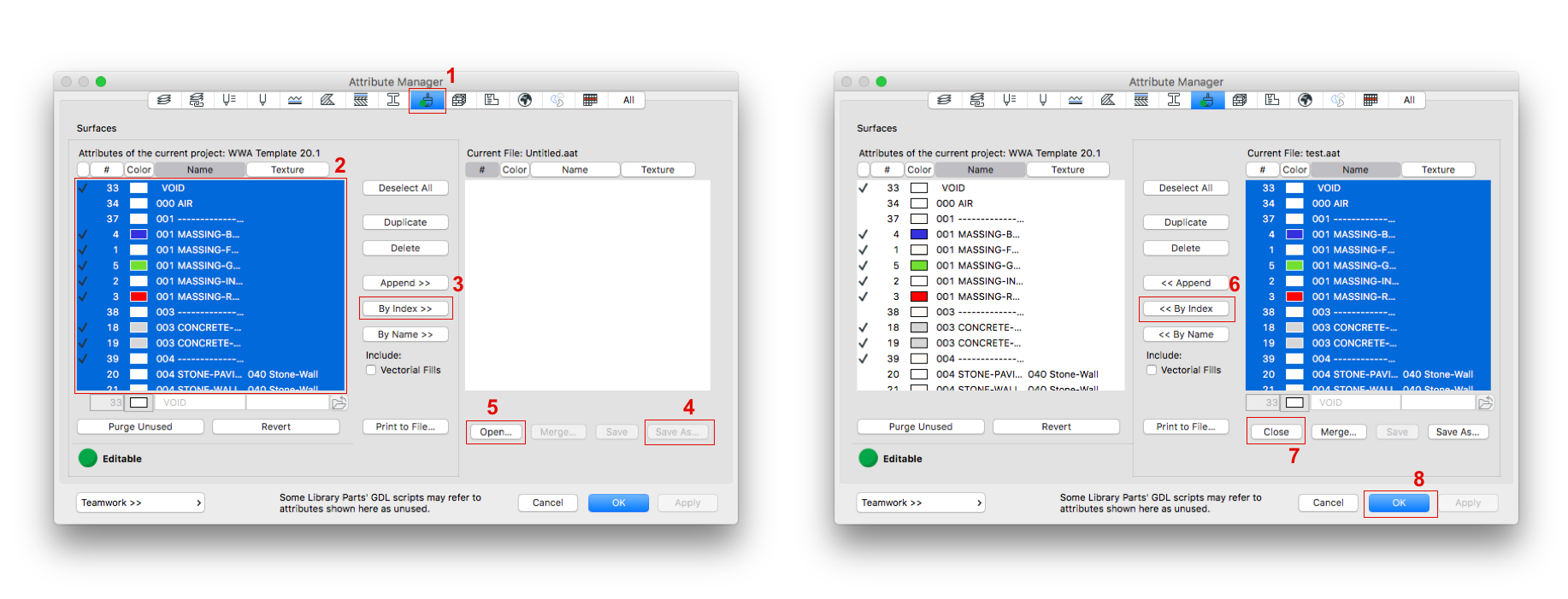
If the pollution occurs anyway, it needs be cleaned up before it starts to impact productivity, and certainly before new attributes are generated. For the most part, the clean up is simple. Open the Library Manager (File > Library Manager), track down any folder/subfolder containing a file with the name (or name similar to) Master_GDL.gdl. This can almost always be tracked to a folder called “From 201101”.C-WWA Library.png

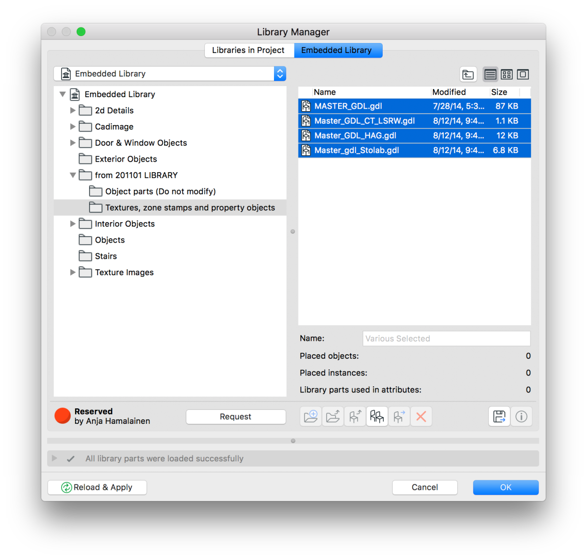
Once these files and folders are purged, open the attribute manager and delete any polluted attributes. It is usually easiest to sort the surfaces by name, as the polluted attributes almost always show after the default surfaces due to naming convention. But any attribute that stands out as out of place should be deleted. The offending attributes are usually italicized and have very odd seeming names. These can just be deleted, rather than delete + replace, since they shouldn’t be used anyway.

B-WWA Polluted.png

If a file uses hotlink modules, this can be a little more complicated. Because hotlinks have their own Embedded Library folder that can not be edited in a host library, there is a different process. The host file needs to be cleared of all modules. I recommend marking module locations with polylines, fills, and/or hotspots before deleting. After the modules are removed, verify that the module libraries are gone, and there are no additional offending Master_GDL parts in any other libraries. Then clean up the attributes.

Next, open all module source files, and run the clean up there; purging libraries and attributes. I also recommend running an attribute match again after all files are clean. Once all files are clean, new modules need to be saved. Do not save over the top of old modules. It is best to create a completely new and clean module.

Lastly, open the host (site) file again, and replace and relocate all modules. Obviously, this issue is compounded even more with projects using nested modules.

Other considerations

Because the Master_GDL objects are so infectious, it is important to stay on top of keeping these things clean. They really are like a disease. We had all current projects clean, but they are rearing their heads again. It is important to be aware of consequences when copying/pasting from one file to another. No two projects have identical attributes, so any copy/paste is likely to bring attributes. If the file is polluted, it will bring in attributes not even used by the copied content.

Interesting Composite Glitch

This is an interesting glitch we ran into today in a migrated project (started in AC16, now in AC20). The file runs pretty well for having passed through so many versions of AC, but there is an interesting error in the composites, one that I was able to replicate to some degree even in AC21 (non-migrated file).

If a composites skin separator is set to “off”, it may appear correct in the plan view (view map or project map), but show with remnants of the skin separator in the drawing (view placed to a layout).

Screen Shot 2017-09-14 at 6.29.07 PM

In the image above, the line selected is deselected, and even though the pen is set to “21”, which is a white skin separator pen in our template, the glitch occurs.

Screen Shot 2017-09-14 at 6.29.21 PM

As you can see above, the composite shows correctly with no skin separators.

Screen Shot 2017-09-14 at 6.29.33 PM

However, once placed onto a layout, the skin separator shows in places. Some composites, depending on skin settings and line/pen types, show up.

Screen Shot 2017-09-14 at 6.29.52 PM

However, by turning the skin separator “on”, as in the image above, and setting all hidden separators to pen 21/41/61 (depending on composite type), we can achieve the desired results, as seen in the image of the placed drawing below.

Screen Shot 2017-09-14 at 6.31.30 PM

Multiple Files & Attribute Matching

Attribute management between files for a single project is critical. If attribute numbers do not match from a building file to a site file, or between multiple building files of a single project, the Hotlink Modules will not appear correct. Surfaces of a module may show incorrectly, or be missing, custom profile beams/columns/walls can become reassigned to a new shape, and composites can switch to a different width if not properly matched.

It is important to note, the attribute number is how attributes are assigned to elements. For example, if your building file has attribute #10 as a stone, but the site file has attribute #10 as a wood, the buildings file will show correctly as stone, but when the building is saved to a .mod and placed to the site, all stone will switch to wood. If attribute #10 doesn’t exist in the site file, the stone will show as a purple & black checkered pattern, indicating the surface is missing.

Attribute Matching

To prevent these errors we have introduced an Attributes file into our workflow for each multi-file project. All attributes (Fills, Line Types, Composites, Custom Profiles, and especially Surfaces) will be generated in this central Attributes teamwork file, then using the Attribute Manager will be matched to all other files for that project on the BIM Server. This does mean a little more management up front, and involves a couple extra steps in managing the project. But the results are a lot less headache on the back end when publishing BIMx, or linking Views from a Site File to the Layout Book of the Buildings File. This is especially critical where projects get so large they require multiple building files, or even multiple site files; which is becoming increasingly commonplace.

Please note, the use of a dedicated Attributes file is not an option or choice to be used (or not) by each team. This is the standard we are using to manage attributes between files at WWA, and a dedicated attribute file has been created in your BIM Server folder if your project program requires one. A little extra time to do this right will ensure we do not need to stop and do things over when our BIMx, PDF and DWG files don’t show correctly due to poor attribute management.

Please watch for an update to our BIM Manual for instructions on how to properly use the dedicated Attribute file.

Custom Surfaces for CineRender

There are quite a few resources for ready made CineRender compatible surfaces. We have 2 catalogues of surfaces in our library folders. If you want to develop a new surface from scratch, you need to duplicate an existing surface, or create a new surface from the Library Catalogs and then edit it. In this exercise, we will be duplicating our basic massing surface to create a new stone surface.

Surf_new

Fig 1.0 Creating New Surfaces

Once the surface has been created by duplicating a previous surface it can be manipulated and edited to include the correct image and render out properly in CineRender, ARCHICAD’s 3D window, and BIMx.

Surf_set1

Fig 2.0 New “Duplicated” Surface

The first thing to do after creating the surface is to apply a Surface Texture. This can be an image from our Arroway texture catalog (FS01 > WW AC Library > 01 Arroway Textures), or from a custom photoshopped image. For this example, I am using an Arroway image and its corresponding bump map image (for the CineRender settings).

After the Surface Texture is applied, you can start to play with the scale, light settings, and transparency. For solid surfaces, transparency should always be set to 0. Emission Attenuation is not completely relevant, unless you are applying an Emission Color to the surface. This can be a very helpful effect if you want to alter the color of a surface, just be aware that the surface is actually emitting a color with this setting. Below are some examples of various Emission Color Settings. Note that, in order to get the surface to match the original image, the Emission Color should be black, or as dark as possible.

For this Surface, we are simply going to leave the Emission Color Black with no Attenuation. With a black Emission, you will get a solid black surface until you apply Reflection and Glowing Settings. After years of trial and error, I have found that the ideal Reflection Settings for semi-matte surfaces are:

  • Ambient = 75-85
  • Diffuse = 75-87
  • Shininess = 8-15
  • Specular Glowing = 0-12

Lastly, if you have a bump map image for the surface, make sure you check Bump Mapping under Alpha Channel Effects. This will define a bump map option in the CineRender settings when matched to the Internal Engine. A bump map image is easy to generate in photoshop with the threshold filter. Keep in mind that the lightest parts of the map are the closest, or the “bumps”; and the darker portions are the recesses.

From here, lets just switch over to the CineRender settings and match. Simply click Match Settings… and choose Update CineRender Settings (from Internal).

Match Settings_Cinerender

Fig 5.1 CineRender Settings

Match_update CineRender

Fig 5.2 Match CineRender from Internal Settings

From here, you can go to the Bump map tab, and change the image to the correct black and white bump map from the Arroway Catalogue, or one that you have created for a custom surface. The Bump Map and the main image file need to align perfectly and be saved at the same size and resolution.

You can check that they are both being aligned and resized properly in the Size tab of the CineRender Settings. You can click on the more Info “…” to the right of the line that reads Use Image Proportion:

Apply Bump_Surf Images

Fig 6.0 Surface Sizes used in CineRender Settings

You can quickly adjust and test the intensity of the bump map by doing quick “outdoor daylight” renderings of a single element or surface. With a little luck and lots of trial and error, you can come up with a surface that maps out correctly and looks good in all views and formats it will be used in!

WALL_RENDERED

Fig 7.0 Rendered Stone Surface


Missing Fills

Missing surfaces come up frequently, since they are most obvious when looking at the model. But any missing attributes can cause problems. Missing fills can cause issues with library parts not reading properly, and can cause files to slow down.

Fills are also a sub-attribute to surfaces for elevations, sections, and interior elevations. This can be a problem, since the missing fill can often be represented by an undesired fill surface fill in the elevation view. In example below, the fill that went missing was a surface fill for a tub filler. It was supposed to be a simple screened fill, but had been replaced with a really complicated detail fill, as the default “next closest fill number”.

Surface Missing Fill

Surface has Missing Vectorial Hatching (Surface Fill)


285Mb

The PDF Generated with an Incorrect Fill is 285 MB


42Kb

Once the Surface Vectorial Hatching is Corrected, the PDF is 42KB

Apply to All – Edge Settings

If you have adjusted edge surfaces of a slab or roof and want to make them uniform, there is an apply to all check box in the element selection settings. This option is also available for morphs using multiple surfaces on a single element. The check box is at the bottom of the element selection settings (Com + T on most work environments), and appears when you change a surface type for an element using multiple surfaces.

Screen Shot 2016-04-05 at 10.24.08 AM

There is an indication that multiple surfaces have been used for a specific surface override shown as a yellow/red square stack to the left of the override setting.

This slideshow requires JavaScript.

For some, this may be getting ahead a bit. If you are unfamiliar with editing individual faces of a morph, slab or roof here are the methods for each:

  • For Morph Elements, hold Cntrl + Shift and click on a morph face(s). Then open the selection settings (Com + T) and edit the surface. If a morph face is already using a desired surface you can use the pick up & inject parameter functions to “eye dropper” surface settings to individual morph faces.
  • For slab and roof settings simply click on the edge of the reference plane and select the top right icon on the pet palette, or the “Custom Edge Settings” button.

Screen Shot 2016-04-05 at 10.14.18 AM

Depending on wether the edge is part of a roof or slab, you will get different options in the resulting dialogue, but the surface adjustments are available for both:

This slideshow requires JavaScript.

Keeping it Clean Part III: The Sandbox

You may recall the posts on keeping your library clean; here and here. But maintaining a clean, legible, and highly functional BIM file is more than just library management. It is also awareness of the attributes, and keeping those properly organized, sorted, named and vetted.

When creating an attribute it should be named and numbered appropriately for clear function, intent and organization. But attributes can become polluted, just like the libraries. This happens when bringing in downloaded objects which contain their own attributes or new attribute references, or when copying/pasting content from one ARCHICAD file into your working project.

Attributes are almost certainly going to come in in either case. So you can either bring the content in, then fix the libraries and attributes, or you can create a quick sandbox to preview and pre-clean the content.

To do this, simply select file > new, and set the resulting window use the latest project settings and launch in a new instance. This ensures the attributes and settings will match your current project for assessing the damage of copy/paste before traumatizing your project.Screen Shot 2015-07-31 at 1.27.13 PM

Once the content has been pasted or added to the sandbox file, review the embedded library for stray or polluted content, and the attribute manager for content that came in with the content.

In the attribute manager, look for any attributes (typically under lines, fills and surfaces) that have come in with the paste. These will typically show at the bottom of the list when sorting by attribute ID. Look for attributes with big gaps in ID sequence, or attributes underlined or italicized in the case of teamwork projects.

Screen Shot 2015-07-31 at 3.08.01 PM

Once these attributes have been removed in the attribute manager, simply search for any content with missing attributes (find & select works wonders for this), and reassign attributes that will copy/paste into your working project file.

Screen Shot 2015-07-31 at 3.09.54 PM

This is a little work up front, but will save tons of time on the back side trying to make sense of the project attributes and figuring out which attributes your project needs and which ones came in through sloppy copy/paste practices.

Attribute & Element Relationships

I know this is a little bit of a fluff piece, but yesterday’s post on the difference between surfaces on a beam vs. morph got me thinking on ways that attributes relate to each other and how they relate to modeling & drafting elements.

Some attributes relate to other attributes. These attributes that collect attributes are sometimes referred to as “super attributes”. It may be surprising which attributes collect the most other attributes (spoiler, the winner is the custom profile!). Attributes primary function, however, is to define the appearance and geometry of the modeling and drafting elements. Some elements actually collect, use and reference other elements, such as the relationship between doors and windows and walls or skylights and roofs. Again, the modeling/drafting element which uses and compiles the most other elements (and attributes) may be surprising. This time its the Zone.

I apologize for the lack of clarity in the following diagram, but a traditional relationship chart started to look like a drunk spider weaving a web. Attribute naming & numbering is red, Elements are blue… Notice attributes never depend on elements, but may use other attributes to define their parameters:Screen Shot 2015-06-09 at 3.45.41 PM

Morph Surfaces & Sloped Elements

When converting elements to morphs it is important to understand how morphs deal with surfaces. They will inherit the settings, orientation & scale of the elements they were converted from. Specifically this article will focus on converting beams to morphs, and the resulting surface alignment. Beams handle surfaces relative to their angle. This works well when you have a wood grain that you want to show sloped with the beam; the grain is angled with the slope of the beam, even after converting to a morph.

Screen Shot 2015-06-08 at 12.47.20 PMIt doesn’t work so well when you have a pattern which is intended to be horizontal. We were recently using morphs as a patch element for an abbreviated overhanging barge. The morph needed to match the siding. When first converting the beam to a morph, the siding was sloped, just like the beam, where the siding on the wall that the morph was associated with needed to be horizontal.

Screen Shot 2015-06-08 at 12.48.04 PMThere are two ways to correct this surface error. The first is to create the morph from scratch rather than converting from another object. This has the added bonus that the morph pen, fill and surface settings will all be set based on the morph tool settings, not the default translator settings. This includes the surface orientation and origin point. If the sloped beam has already been placed it is very simple to trace out the beam with the morph tool and extrude to the width needed.

Screen Shot 2015-06-08 at 12.48.31 PM

Screen Shot 2015-06-08 at 12.48.41 PMThe next way to correct sloping surfaces from converted morph elements is to simply reset the surface after the element has been converted. This is in the morphs selection settings under the model drop down section.

Screen Shot 2015-06-08 at 12.49.01 PM

The result is similar, if not identical to creating a morph from scratch.

Screen Shot 2015-06-08 at 12.48.51 PM

This method also solves morphs that have been rotated after creating them. A morph will maintain its surface orientation relative to its original geometry. This means that if you rotate a morph, its surface appearance will rotate with it. To get the surface back to their correct orientation you will need to either rebuild the morph or reset the surfaces in the selection settings.