The trick is to set the window operation to “door”!
Showing Window Operations in Plan
Leave a reply

The trick is to set the window operation to “door”!
10 years ago, this is how we mitered trim in Archicad:
https://wwabim.wordpress.com/2014/10/16/mitered-trim/
Fast forward to today, and here is the current method for cutting end angles of beams and columns!
https://youtu.be/vPbKnRNlIHs
Archicad default Section, Elevation, and Interior Elevation markers do not have a control for “line type” parameters. As a result, many files end up with dashed lines within the marker head.
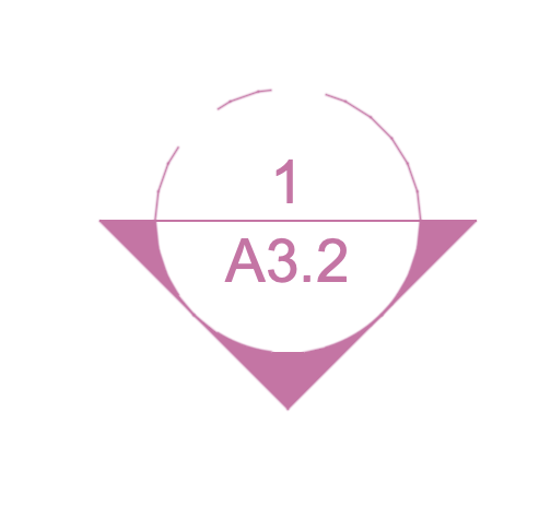
All attempts at reindexing, filling gaps in indexing, etc. have not fixed this. In some cases, reverting to the favorites or copying a marker from a working file, has resolved this; however, this has not always worked.
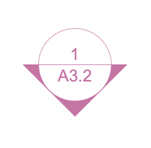
As an alternative work-around in a recent project experiencing this issue, I have added a Graphic Override rule to all GO view settings to change all marker element’s line types to Solid Line.
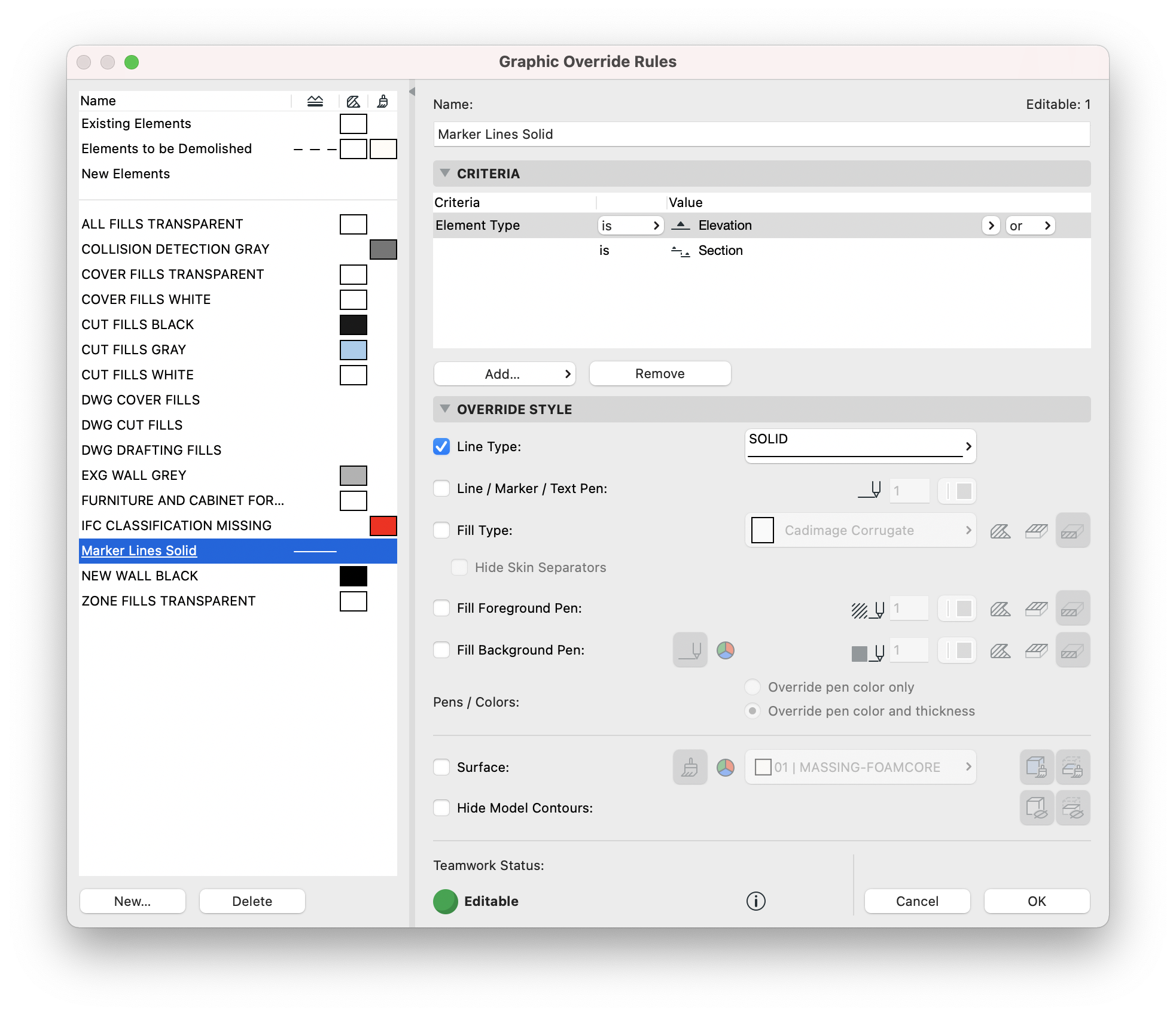
This results in marker line types showing solid for all views that this rule is applied to.
We have reviewed teh session/error report tab several times over the years; here for example.
But recently, I’ve been finding errors tied to missing bMats (building materials) in settings that are often times ‘locked out’ or even hidden by parameter setting combinations. In cleaning and running maintenance on a file recently, I found over 100 error lines in the session report tied to such parameters in railings, doors, windows, and stairs. One solution was to add and reindex ‘dummy’ bMats to fill the gaps and get them back on track; but when they are buried or hidden, that doesn’t always work. Here is the solution for those instances:
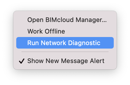
Occasionally, Archicad will get disconnected from the BIM server. This can happen due to internet or VPN connection issues. When you are able to reconnect to the internet, network, and/or VPN, you may need to reconnect your local data. To do this, make sure the teamwork pallet is open in your workspace, and check the file connection status at the top of the pallet:


Some projects have been seeing text (text tool, labels, and dimensions) go missing. There are several work-arounds and even solutions for this. More than anything, this further emphasizes the need to review all pdf’s before sending documents to plot or email.
If your documents look like the screen shot here (there should be a LOT more than just “HRDWR” in this detail); you can try one of the following:
-Print to pdf, seems more reliable than save as or publisher.
-Use Arial font. Helvetica seems more susceptible to this glitch.
-Reload the project from the server (teamwork > project > reload from server). It seems to be tied to the local data and font file communications
-Have another team member publish, or publish from their computer. It is device, not file, specific.
-If all else fails… restart. Turn it off and back on again fixes everything!

It has long been assumed that skylights, much like a lot of AC elements, will not associate to zones, or at least not show their association in the schedule field. A thread on a forum I recently stumbled across pointed out that using the “trim to roof” option to crop zones to the roof, rather than the normal Solid Element Operations, will effectively show the zone/skylight association in schedules:
Drafting and masking fills are occasionally necessary to make our plans clean and tidy in final documents. It is important to use the correct fill category though. In the attached screen shots, we are preparing marketing and presentation plans, and fills are helping out the stairs; but the fills applied were cut fills, so they show as black pochè when the presentation plan Graphic Override is applied. Cut fills should be reserved for building materials, cover fills for surfaces, and drafting fills for drafting.


The multiply tool is a great feature for quickly copying multiple elements along equal divisions or distances, but you can also use it to make multiple copies along a pre-defined vector!
There is an issue in migrated files using the Cadimage roof covering add-on that has resulted in many of our projects showing a 0″ thickness plane offset below the roof plane.

This is a result of the soffit subsection not wanting a value of 0. You can set the soffit thickness to any positive value and the soffit goes away, as long as all other values in the soffit section remain at 0″.


