Tag Archives: CineRender

New Surface from Internal Settings

Getting a surface image or color to render out properly can be difficult due to the number of variables that need to be managed. I have gone through a basic exercise to explore 4 different surface settings for reflection to compare results on surface color in Open GL and CineRender views. The surfaces I generated are a basic medium gray and a bone white surface with varied reflection and emission settings.

For the purposes of this exercise, I have eliminated all Transparency and Emission variables, and only made adjustments to the Reflection and Glowing Settings. By playing with the Specular Color, you can further adjust the hue of the CineRender view.

screen-shot-2016-11-11-at-11-29-53-am

Matte Settings

screen-shot-2016-11-11-at-11-29-57-am

Semi-Gloss Settings

screen-shot-2016-11-11-at-11-30-02-am

High Gloss Settings

screen-shot-2016-11-11-at-11-30-06-am

Mirror Settings

Note that the final color of the rendered view is impacted to varying degrees based on the reflection settings. Further adjustments can also impact the color, intensity, reflectivity of the surfaces include: Lamp Settings and location and hue, Rendering Engine preset, Rendering Sky Preset, and Surface Color.

open-gl-3d-window

Open GL View

outdoor-with-lamps

CineRender Outdoor Daylight Medium + Lamps 50%

Custom Surfaces for CineRender

There are quite a few resources for ready made CineRender compatible surfaces. We have 2 catalogues of surfaces in our library folders. If you want to develop a new surface from scratch, you need to duplicate an existing surface, or create a new surface from the Library Catalogs and then edit it. In this exercise, we will be duplicating our basic massing surface to create a new stone surface.

Surf_new

Fig 1.0 Creating New Surfaces

Once the surface has been created by duplicating a previous surface it can be manipulated and edited to include the correct image and render out properly in CineRender, ARCHICAD’s 3D window, and BIMx.

Surf_set1

Fig 2.0 New “Duplicated” Surface

The first thing to do after creating the surface is to apply a Surface Texture. This can be an image from our Arroway texture catalog (FS01 > WW AC Library > 01 Arroway Textures), or from a custom photoshopped image. For this example, I am using an Arroway image and its corresponding bump map image (for the CineRender settings).

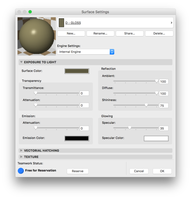
After the Surface Texture is applied, you can start to play with the scale, light settings, and transparency. For solid surfaces, transparency should always be set to 0. Emission Attenuation is not completely relevant, unless you are applying an Emission Color to the surface. This can be a very helpful effect if you want to alter the color of a surface, just be aware that the surface is actually emitting a color with this setting. Below are some examples of various Emission Color Settings. Note that, in order to get the surface to match the original image, the Emission Color should be black, or as dark as possible.

For this Surface, we are simply going to leave the Emission Color Black with no Attenuation. With a black Emission, you will get a solid black surface until you apply Reflection and Glowing Settings. After years of trial and error, I have found that the ideal Reflection Settings for semi-matte surfaces are:

  • Ambient = 75-85
  • Diffuse = 75-87
  • Shininess = 8-15
  • Specular Glowing = 0-12

Lastly, if you have a bump map image for the surface, make sure you check Bump Mapping under Alpha Channel Effects. This will define a bump map option in the CineRender settings when matched to the Internal Engine. A bump map image is easy to generate in photoshop with the threshold filter. Keep in mind that the lightest parts of the map are the closest, or the “bumps”; and the darker portions are the recesses.

From here, lets just switch over to the CineRender settings and match. Simply click Match Settings… and choose Update CineRender Settings (from Internal).

Match Settings_Cinerender

Fig 5.1 CineRender Settings

Match_update CineRender

Fig 5.2 Match CineRender from Internal Settings

From here, you can go to the Bump map tab, and change the image to the correct black and white bump map from the Arroway Catalogue, or one that you have created for a custom surface. The Bump Map and the main image file need to align perfectly and be saved at the same size and resolution.

You can check that they are both being aligned and resized properly in the Size tab of the CineRender Settings. You can click on the more Info “…” to the right of the line that reads Use Image Proportion:

Apply Bump_Surf Images

Fig 6.0 Surface Sizes used in CineRender Settings

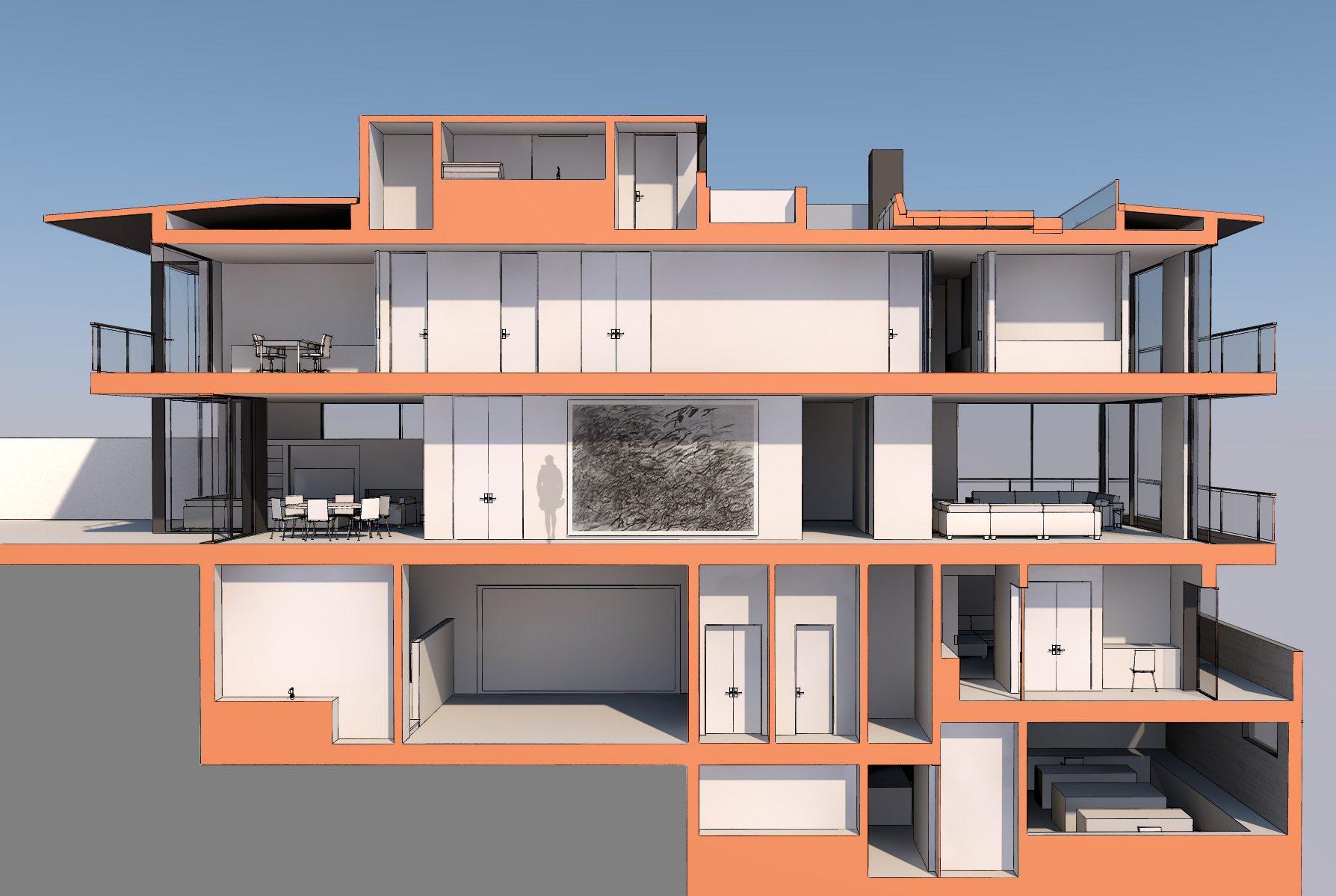
You can quickly adjust and test the intensity of the bump map by doing quick “outdoor daylight” renderings of a single element or surface. With a little luck and lots of trial and error, you can come up with a surface that maps out correctly and looks good in all views and formats it will be used in!

WALL_RENDERED

Fig 7.0 Rendered Stone Surface


CineRender Subtleties

There are many presets in the CineRender settings of ARCHICAD, and most of them work really well out of the box. But you can make some very minor adjustments to the settings without loosing the overall character and quality of the rendering, but only changing the general lighting and feel of the final image.

An example of this is in the preset sky. The following images were both started from the Indoor Daylight Medium (Physical) preset. The first is an out of the box rendering:

Diamond Head Furniture Rendering2

A very nice rendering, but the color felt a little warm and pink to me. So I switched the weather preset from Clear to Friendly Afternoon. The result is a slightly cooler, almost blue feeling space with deeper shadows.

Diamond Head Furniture Rendering1

If you do find a slight adjustment you prefer to the out of the box settings, be sure to save it as a preset to quickly get back to those settings in the future.

Screen Shot 2015-09-10 at 11.55.13 AM

Cinerender Background

Cinerenders presets are pretty awesome; I am not a huge fan of the Weather Preset names or the background associated with them, but I do love the light and shadow affects these Weather Presets have on the final rendering.

So how do you keep the cool light and shadow casting, but replace or eliminate the background? It is a simple toggle in the detailed settings or the rendering settings dialog. Unchecking the Sky Visibility under Environment > Physical Sky > Compositing will change the sky to match the background to match the default background settings at the bottom of the dialog. In this example it is set to None, but it could also be set to a color(s) or an external image.Screen Shot 2015-09-02 at 1.23.26 PM

Leaving it white, as in the example above, enables a quicker photoshop clean up to add a post production background.

Another Rendering Example

Maggie has been doing some pretty incredible renderings for her project, as I mentioned (and she demonstrated) in the last staff meeting. Just to showcase some of those, and give a comparison of how you can take your renderings to a new level of awesomeness, here are her updated images!

The “improved” version of these images started as the CineRender Indoor Daylight Medium Physical preset with a few minor adjustments, like turning lamps on. None of these images uses any photoshop post rendering adjustment.

Default CineRender Indoor Daylight Fast Rendering:

01 1BR Common Room

Updated objects, new surfaces, lamp elements & adjusted rendering settings:

1BR Cottage common room

Default CineRender Indoor Daylight Fast Rendering:

Barn Bunkhouse 01

Updated objects, new surfaces, lamp elements & adjusted rendering settings:
Barn bunkroom entry

Default CineRender Indoor Daylight Fast Rendering:

Barn Bunkhouse 02

Updated objects, new surfaces, lamp elements & adjusted rendering settings:

Barn bunkroom bed elevation

Just a little attention to detail, the right objects and leveraging the lamp tool makes a huge difference!

Another Rendering Example

Afra has recently done a couple of section cut renderings to illustrate two options for an art wall for the Pacific remodel. The cut fill set as orange is set by the Filter & Cut Elements in 3D options under the View  > Elements in 3D View menu. The renderings were then produced using the Cinerender Engine and a little photoshop. Here is Afra’s description:

“The two options I’ve prepared for the client are attached. They emailed us this morning to let us know they’re thinking about buying a rather large painting and currently debating where it could be located in their new house. They asked us to produce a couple of elevation studies ASAP to help them make their decision. 
They sent us a jpg of the painting, so these images are just a combination of rendering, outlines, and a little bit of photoshop. Overall, pretty simple!”

painting-option-east-wall painting-option-west-wall

MATCHING CINERENDER TO INTERNAL ENGINE

If you apply an image as a surface to you internal engines surface settings verify the image file name has no “special” characters; they don’t play well with CineRender!

In the below image you can see the surface views perfectly in the internal engine surface preview, and even applies to associated surfaces in the model without any issue.

Internal Engine 1

Now when we open the CineRender by MAXON Engine Settings and Match Settings > CineRender to match from Internal…

CineRender 1

the preview blacks out and the view will not render. The rendering window will open and run for about 7-8 seconds then finish with a blank screen.

CineRender 2

The solution is a simple one, in your library manager verify all images to be used in renderings have no special characters (\ / , ‘ ” _ | – etc.), the jpg or png should be named with letters, numbers, and spaces only! You can save the offending surfaces to your desk top, rename and reload. It may also be worth the effort to verify file size and location in the embedded library at this time; in the interest of maximizing file efficiency and minimizing file size.

CREATING TRANSPARENT AND SCREENED SURFACES

CREATE A PNG WITH TRANSPARENCY IN PHOTOSHOP

First, open the texture you want to modify in photoshop.  Create transparent voids using whatever method you like to select and delete portions of the texture (One method is to use the Magic Wand with “Contiguous” un-checked to select. Another method is to use the Select > Color Range tool).  Make sure that when you delete these areas, you see the white and gray checkered background that denotes transparency in Photoshop.  Flatten and save the file as a .png.

Step 1 - Photoshop

APPLY THE SURFACE IMAGE TO THE SURFACE SETTINGS

Using the Library Manager, upload the surface to a surface or textures folder in the Embedded Library. Then, in the Surface Settings dialog, create or duplicate a surface while in the Internal Engine settings and add the image using the search command in the Texture section.

There are only two steps for the “screen” effect:

1. Check “Transparency” in the alpha channel effects area.  This determines whether the voids you created in your .png display as opaque white spots or truly transparent voids.

2. Decide whether to use the “Transmittance” parameter.  This parameter has two effects.  The first effect determines whether or not the surface casts a shadow.  At 0, the surface casts shadows like a normal opaque surface.  You might want to stick with 0 if you have a very dense material, like a dense rain screen that will cast a heavy shadow in real life.  The second effect is the degree of transparency of the material.  At a value of 1, the surface stops casting shadows entirely, but the solid portions of the texture are still completely opaque.  This is useful for lighter meshes or screens that will only cast a faint shadow.  (Unfortunately, there are no degrees of shade in Archicad’s internal engine – shadows are only either on or off.)  At higher values of transmittance, the surface becomes increasingly more transparent, which can be used to tune how well you can see beyond the surface and correct for a texture that is too dense/dark.  At 100, the surface is completely invisible (and mostly useless).

Step 2 - Surface Opaque

Step 3 - Surface w Alpha Transparency

Step 4 - Surface w Transmittance

MATCH THE SETTINGS FROM INTERNAL TO CINERENDER

Once the on screen view (internal engine) is set to the correct scale, transparency, reflection, etc., switch to the CineRender surface settings and match CineRender from Internal Engine. A quick, low resolution test will show wether the match is correct for rendering. I recommend rendering these tests at 150 dpi or less using the “Outdoor Daylight Fast” preset; this will give you a reasonable quality view in less than 60 seconds.

– PV / PJM

NEW CINERENDER SAMPLES FROM AC18

This is really just a show piece to share some of the great work that has been quickly produced by Boyce and Rob using an ArchiCAD 18 study model to produce quick and beautiful renderings. They adjusted a few of the rendering settings and created a variety of warm to cool feeling images of a single room. Adjusting some of the surface settings allowed them to create the reflective surfaces that represent the glass shower partition and glass clad interior walls.

render07_cropped_green render07_cropped render08_cropped_green render08_cropped