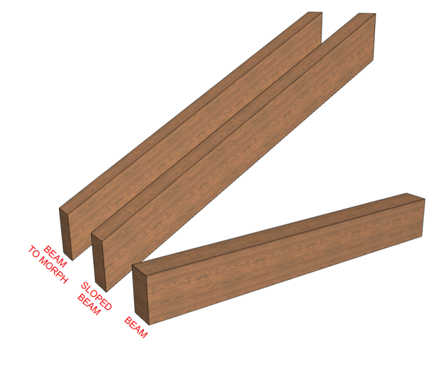
When converting elements to morphs it is important to understand how morphs deal with surfaces. They will inherit the settings, orientation & scale of the elements they were converted from. Specifically this article will focus on converting beams to morphs, and the resulting surface alignment. Beams handle surfaces relative to their angle. This works well when you have a wood grain that you want to show sloped with the beam; the grain is angled with the slope of the beam, even after converting to a morph.
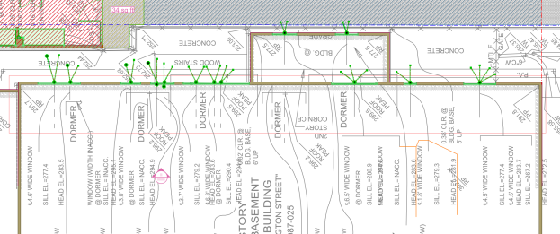
 It doesn’t work so well when you have a pattern which is intended to be horizontal. We were recently using morphs as a patch element for an abbreviated overhanging barge. The morph needed to match the siding. When first converting the beam to a morph, the siding was sloped, just like the beam, where the siding on the wall that the morph was associated with needed to be horizontal.
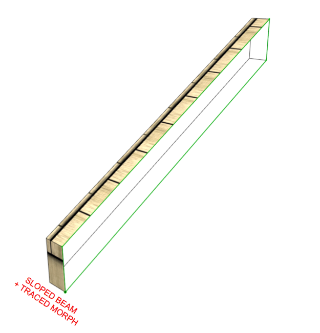
 There are two ways to correct this surface error. The first is to create the morph from scratch rather than converting from another object. This has the added bonus that the morph pen, fill and surface settings will all be set based on the morph tool settings, not the default translator settings. This includes the surface orientation and origin point. If the sloped beam has already been placed it is very simple to trace out the beam with the morph tool and extrude to the width needed.
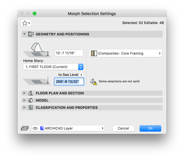
 The next way to correct sloping surfaces from converted morph elements is to simply reset the surface after the element has been converted. This is in the morphs selection settings under the model drop down section.
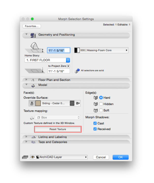
The result is similar, if not identical to creating a morph from scratch.

This method also solves morphs that have been rotated after creating them. A morph will maintain its surface orientation relative to its original geometry. This means that if you rotate a morph, its surface appearance will rotate with it. To get the surface back to their correct orientation you will need to either rebuild the morph or reset the surfaces in the selection settings.