Tag Archives: Detailed Model

Isolating Elements

Working efficiently in ARCHICAD boils down to isolating out only the portions of the model you need to view. Viewing the entire model at all times is inefficient and ineffective, since plans can look to cluttered, 3d can be too slow, and section and elevation views may show more content than is relevant to the work that needs to be done.

Isolating elements out is done by the following methods (and different methods may be more useful in certain views than others):

  1. By Selection
  2. By Marquee
  3. By Layers
  4. By Renovation Status (not shown in video below)
  5. By Filter and Cut in 3d Palette
  6. By Cutting Planes

The following video quickly covers most of these methods of isolating elements in plan and 3d.

Thinking Outside the Box

A few weeks ago I gave an example from Rina & Maggie’s project using a fence object, complex profile, or morph object in place of multiple column elements.

Here is another example of that creative thinking. Using that same fence object Matthew placed dentils on his crown, making light work of what would have otherwise been incredibly tedious to place individual dentils. Of additional benefit, the spacing and “slat” dimensions are set right in the object, so spacing and sizing changes can be made and overall spans can be adjusted globally or per section of crown.

Screen Shot 2015-06-26 at 2.13.49 PM

Granted, we don’t do a lot of trim packages involving dentils, but this is the sort of out of the box thinking that can gain massive amounts of efficiency for any design. Using the right tool for the job is crucial to maximize efficiency, precision and flexibility.

Screen Shot 2015-06-26 at 2.14.52 PM

SEO GENERAL NOTES

Today a file had mysterious missing walls and floors after the site had been inserted and trimmed to the building. After looking into it, the operator for the site trim was a slab the height of the building.

Screen Shot 2014-11-13 at 4.19.03 PM

There are a few words of advice I will share with everyone regarding using solid element operators:

First, and most closely related to this issue is, that if you have a building element already in place (in this case the floor slab and basement walls) that can act as the operator, use it. It is not necessary to turn an operator off once the operation has been made, it can be part of the final building model and visible in all views.

Next, an operator that is not associated with a building element and is actually on the SEO layer should be as minimum as possible. As you may remember from the post on trimming door and window casings, we used a single plane morph object as the operator. The operator should be as simple as possible to perform its function.

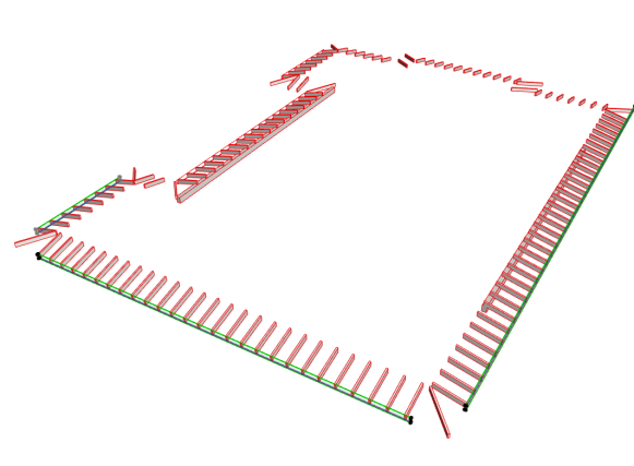
The last note on using solid element operators is to use operators that relate only to their targets. As an example of this, we often see rafter tails trimmed by a profiled beam or wall. A rafter tail should never be associated as a target of an operator located on the other side of the building or along another wall line. In the image below Maggie has used a single operator for all rafters along each wall face, rather than selecting all rafter tails and all SEO beams and performing a single blanket operation.

Screen Shot 2014-11-13 at 4.39.43 PM

MATCHING BEAM ANGLES TO ROOF SLOPES

Recently a question about beam and roof matching has come up. For example, if you place a roof at a 4.75:12 slope, your beam would need to be 21.5953º (and that is missing a few digits) to get close to matching. In the beam settings this would round to 21.60º by default, since we are only able to place beams to a two digit precision.

To match a beam precisely to the roof slope you will need a working section through the roof showing the full length of the roof and beam in an orthogonal elevation view.

Screen Shot 2014-10-27 at 8.14.47 AM

Start by aligning the top node of the bottom slope end of the beam with the appropriate skin or core line of the roof (this does not need to be an end node of the roof, but does need to be snapped to the roof skin separator line). Next select the top node of the top slope end of the beam and select the “modify angle” button on the pet pallet. Last move the top node to the same line as the bottom node previously aligned. Note that you will get a checkbox or solid pencil symbol next to the cursor when you are snapped to the line.

The beam settings will still show as rounding to the nearest two decimal places, but the beam will perfectly align with the roof slope no matter how close you zoom in. From here it is a simple eye-dropper and inject command to get the other beams elevations and slopes to match.

I would also like to mention one more time, this is another reason it is critical to give similar or identical items a common element ID to differentiate them from other elements. Using the find and select tool for all beams with an ID of “Typical Rafter” and a beam width of x” will allow you to quickly isolate the beams that need to be modified to match the one that now aligns with the roof.

MITERED TRIM

If you have a complex profile applied to a beam and column to represent your trim, you may find it tricky to get them mitered properly. Notice the overlapping “square” boxes at the intersection in the image below.

Screen Shot 2014-10-16 at 8.23.23 AM

A solution was recently developed by Boyce which quickly resolves the lack of interaction between beams and columns. Insert a morph object as a single plane at a 45º angle through the intersection point. Using this plane as an operator with upward extrusion on the column, and with downward extrusion on the beam you will have a cleanly mitered trim in elevation, section and model views.

Screen Shot 2014-10-16 at 8.26.08 AM

Note the miter line shown in the image below due to different surfaces being applied to the beam and column. This is a bonus tip if you want to express the miter in your documents and model.

Screen Shot 2014-10-16 at 8.27.03 AM

In most cases we will want to see the miter “disappear”. If you apply identical building materials and surfaces to both beam and column the intersections clean up. You will see a line where two curves intersect, but this is due to the handling of curves vs planes. For most instances this profile could be altered to use a plane rather than curve to represent the coved portion of the trim; this wold give a clean intersection across the full miter.Screen Shot 2014-10-16 at 8.27.45 AM