Category Archives: Selection Set

Selecting Elements

Working efficiently in ARCHICAD is critical, but not always easy. There are so many ways to model or draw everything, it is hard to know if you are using the most stream lined process.

A few things can help speed up your modeling and navigation work. In a series I am working on for the next Lunch and Learn presentation, we are going to explore the following:

  1. Efficiently Selecting ARCHICAD elements
  2. Isolating portions of a view
  3. Editing elements and groups of elements
  4. Efficient modeling
  5. Efficient drafting and drawing

The first series is covered here in the following videos:

Selecting Elements –

1) Find and Select

2) Selections Palette

3) Arrow Tool Options

4) Marquee Tool Options

5) Selecting Elements by Tool or Element Type

Doors & Walls – Symbolic or Projected

The symbolic or projected view of a door determines wether it matches the exact 3d settings of the door or is just a graphic plan symbol. There may be cases for both, but it is important to know what the settings do; and find the right combination of settings for both the wall and the door so that they both appear as expected, or in some combinations, appear at all.

screen-shot-2016-10-07-at-10-17-20-am

Wall Projection Settings

screen-shot-2016-10-07-at-10-17-27-am

Door Projection Settings

Below is the break down of what each combination of wall and door settings with 3 different relationships to plan cut plane settings.

screen-shot-2016-10-07-at-10-36-18-am

Walls and Doors Projection Settings

IFC Element Classification

Recently, we have noticed projects exporting IFC files incorrectly; specifically with missing content. Wether this is due to changes to ARCHICAD from IFC2x3 to IFC4, or if it is just a modeling error on our part, is difficult to pinpoint at this time. What we have determined is the issue is the result of Element Classification going missing.

The Element Classification is the little drop down at the bottom of the settings dialogue for each model element. You can locate this within the Categories and Properties tab of the element settings.

screen-shot-2016-09-30-at-1-34-42-pm

It can be easy to ignore this setting, since it really doesn’t impact our typical model or document process. But for IFC coordination this setting is critical. If this goes missing, the element will not save out.

So a missing or undefined classification can get in the way of effective collaboration, but so can an incorrect classification. An example I have seen is doors that were used as gable end vents/walls. Because the door’s classification was left as “Door”, it was read as a door on the Revit side. This resulted in the door and the wall were defined as an opening that penetrated the roof; the engineer had to ask for a correction from our end.

screen-shot-2016-09-30-at-1-53-48-pm

IFC Classifications can seem a little confusing, given the unclear and vague terminology used in describing each classification. But fortunately Bond Bryan has already done the leg work to define each element classification and what is included. I have in turn reinterpreted this list in our BIM Manual for our calibre of projects; you can view this Dictionary of Element Classifications under Collaboration > IFC Classification in our BIM Manual. Or for a more complete list of building components and their Classifications, see Rob’s list here.

All Things Grid Tool

First and most importantly it is essential to realize there are multiple parts to the grid tool and its interaction with the various drawings. The Grid Settings are relatively straight forward and simple to understand.

screen-shot-2016-09-07-at-2-50-36-pm

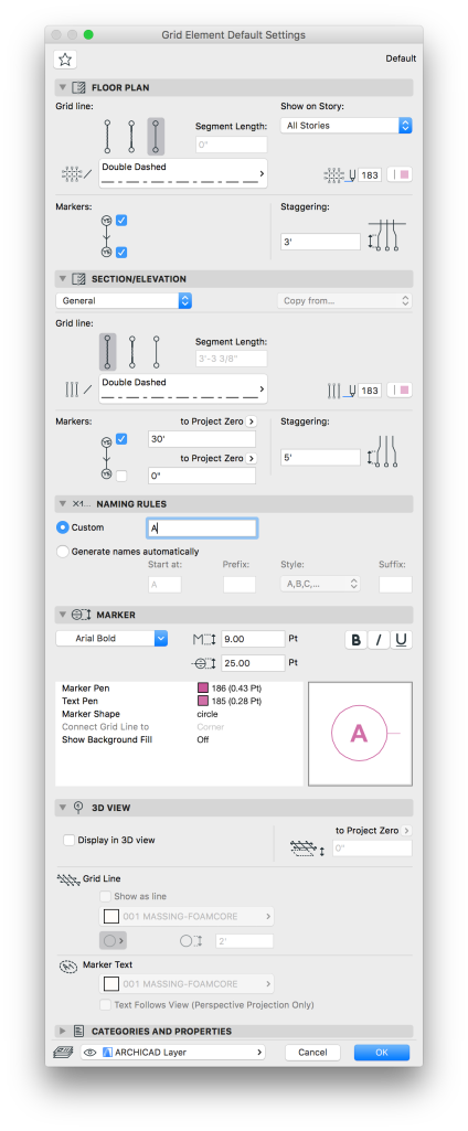
Standard Grid Settings from Template Favorites

Above is an example of our default Grid Element Settings. If you find you do not have a Grid Element in your favorites, you can start with the line types and pen weights shown there. Also note the Naming Rules section; all grid elements have a custom name and are not generated automatically (this requires an automated grid placement that really only works for projects with very regular grids tied to beams and columns).

It is also important to note the upper right corner of the Grid Element Floor Plan Settings dialog. The drop down for Show on Story… allows you to define which stories each grid marker shows up on. I have audited projects in the past that used lines, circles, text, or even duplicate grid elements to selectively show grids on different stories. This drop down allows you to access a custom list of stories to show or hide each grid marker on. For most of our projects, this should be set to all stories for all grids, but if you need to customize this, there is an easy solution in the Grid Element Settings.

The Grid Tool Settings also have a section for Section/Elevation projections of the Grid. It is important to note that these settings DO NOT determine IF the grid will show up on Elevations or Sections, only HOW they will appear on those views.

To properly show Grids on an Elevation or Section, you need to set the Grid Settings in the views Marker Settings.

screen-shot-2016-09-07-at-2-56-55-pm

Elevation Selection Settings for Grid Appearance

To turn on Grids for an Elevation or Section simply go to the Grid Tool section of the Markers Selection Settings and check the box to Show Grid Elements. Make sure that the elevation settings do not have Auto-stagger selected. This feature can be useful, but more times than not it just messes with the opposite views appearance.

As an example, here is a quick mock up of an elevation with a grid offset:

screen-shot-2016-09-07-at-3-00-05-pm

Notice that Grid Element “C” is staggered over the top of Grid Element “B”. This is because the grid has been offset to the left of “B” on the opposite elevation. Staggering a grid element, either manually can cause this overlap. A manual adjustment applies the stagger to all elevation/section views that grid appears on. Automatic staggering should stagger grids appropriately for each view, but any manual changes will revert to the automatic position when the view is refreshed.

In the above example, Grid Element “C” may not need to appear on this elevation, since it is for a structural bearing line that does not relate to this side of the project. In the elevation or section marker settings, this Grid Element can easily be excluded from the Viewpoint of each marker individually. You simply need to go to the Marker Settings and click Selected under Show Grid Elements by Name and exclude the grids you do not want to show on that Viewpoint.

screen-shot-2016-09-07-at-3-00-38-pm

Elevation Settings to Show/Exclude Individual Grid Elements

Apply to All – Edge Settings

If you have adjusted edge surfaces of a slab or roof and want to make them uniform, there is an apply to all check box in the element selection settings. This option is also available for morphs using multiple surfaces on a single element. The check box is at the bottom of the element selection settings (Com + T on most work environments), and appears when you change a surface type for an element using multiple surfaces.

Screen Shot 2016-04-05 at 10.24.08 AM

There is an indication that multiple surfaces have been used for a specific surface override shown as a yellow/red square stack to the left of the override setting.

This slideshow requires JavaScript.

For some, this may be getting ahead a bit. If you are unfamiliar with editing individual faces of a morph, slab or roof here are the methods for each:

  • For Morph Elements, hold Cntrl + Shift and click on a morph face(s). Then open the selection settings (Com + T) and edit the surface. If a morph face is already using a desired surface you can use the pick up & inject parameter functions to “eye dropper” surface settings to individual morph faces.
  • For slab and roof settings simply click on the edge of the reference plane and select the top right icon on the pet palette, or the “Custom Edge Settings” button.

Screen Shot 2016-04-05 at 10.14.18 AM

Depending on wether the edge is part of a roof or slab, you will get different options in the resulting dialogue, but the surface adjustments are available for both:

This slideshow requires JavaScript.

UNIFORM PEN AND LINE TYPES

It has recently been discovered that there is an apparent “change” to ArchiCAD’s vector tools. Where we used to be able to inject parameters between lines, polylines, arcs and splines; in AC v18 it doesn’t seem to act the same way.

There is a solution! In the selection settings for each tool check the box that says “Uniform Settings for Line Tools“.

Quick and easy you are able to inject parameters from a polyline to a line or spline or arc. If you are not aware that this was an option, be sure this box is checked in all your vector tools selection settings and start using the inject parameters features for even more element types.

Screen Shot 2014-10-24 at 2.19.46 PM

EDIT SELECTION SETS

The Selection Set Pallet

The Selection set pallet is often forgotten; and its features have certainly been growing over the past few software versions. Look through some of the options available for editing multiple element types in one click. We can change multiple element types Layers, Pens, IFC function, Inter/Exter Location, Renovation Status and Structural Function.

The Renovation Status function is Incredibly helpful when assigning elements to be demolished early in a remodel project.

If you do not know about this pallet it can be accessed directly through your Info Box, it is the hammer icon to the left of your layer drop down. Play around with this if you don’t use it already, it is a huge time saver!

Screen Shot 2014-09-19 at 9.58.33 AM