Category Archives: Drafting

Drafting Fill Types

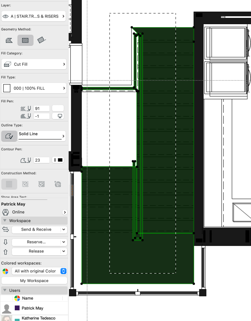
Drafting and masking fills are occasionally necessary to make our plans clean and tidy in final documents. It is important to use the correct fill category though. In the attached screen shots, we are preparing marketing and presentation plans, and fills are helping out the stairs; but the fills applied were cut fills, so they show as black pochè when the presentation plan Graphic Override is applied. Cut fills should be reserved for building materials, cover fills for surfaces, and drafting fills for drafting.

Clean up fills set to “Cut Fill”
Switching fills to “Drafting Fill”

21 ARCHICAD Party Fouls!

There are certain things we should never do in ARCHICAD, or at the very least, avoid at all costs. Here is a brief list of things to never get caught doing in your projects:

  1. DO NOT Mask out and put manual text over a schedule on a layout
  2. DO NOT Put a fill over a sloppy junction in plan or section
  3. DO NOT Draft an elevation element that can/should be modeled
  4. DO NOT Grab all of one element type to set as operators or targets in a solid element operation
  5. DO NOT Work all day or multiple days without a send/receive or save
  6. DO NOT Manually overriding a text dimension rather than tracking down the rogue 1/64″
  7. DO NOT Use the bold marquee to stretch/move/delete unless you intend to edit every visible element on every story in the project
  8. DO NOT Copy/Paste from a file without checking for attribute pollution
  9. DO NOT Store model clutter on a hidden layer unless it will be used in the future
  10. DO NOT Use high resolution images for custom surfaces
  11. DO NOT Import custom GDL/SKP/RFA elements without checking polygon count and file size
  12. DO NOT Model anything farther from project 0,0,0 than necessary
  13. DO NOT Allow the view map to gather disorganized views or floating views outside folders
  14. DO NOT Save views with CUSTOM or MISSING view settings
  15. DO NOT Embed pdf’s and dwg’s in a file unless they are part of the documentation and they have a relatively small file size (10MB max)
  16. DO NOT Ignore the library loading report for missing or duplicated parts
  17. DO NOT Ignore the error report tab
  18. DO NOT Modify existing meshes; only add/subtract with additional model components
  19. DO NOT Save objects as objects/door leafs/etc. for custom GDL parts
  20. DO NOT Use 10 elements to model something where 1 element will work
  21. DO NOT Customize drawing names in place of properly naming the view and/or viewpoint

I’m sure there are plenty of other ‘bad practices’ not included on this list. These are just a few things that happen from time to time, and that we should try to avoid in the future. As always, with ARCHICAD, there are so many ways to approach any modeling and documenting problem, and we should always be looking for the best way possible.

AC 23 Text Frame Changes

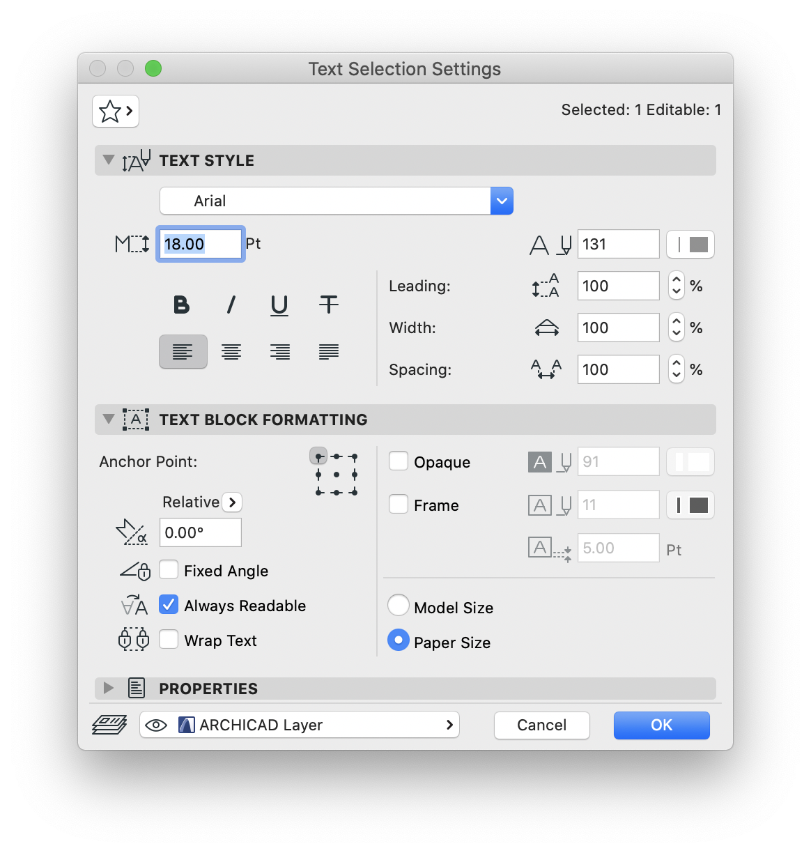
There is a subtle, but important difference between text boxes in AC 23. In previous versions of ARCHICAD, the frame distance could be applied, then the frame turned off. This would allow the text to mask out elements without the need for an additional fill. Text boundaries could still be extended or adjusted, with these settings.

Screen Shot 2020-03-05 at 12.08.01 PM.png

Wether intentionally or not, ARCHICAD 23 works differently, with regard to these settings.

Screen Shot 2020-03-05 at 12.09.53 PM.png

ARCHICAD 23 ignores the 5.00 Pt offset from the above image, but it also locks out the user from adjusting the text boundary, as seen in the first image, with the pet palette activated from the upper right corner of the selected text box. In AC 23, the pet palette will not even be available if there is a frame offset while the frame is off. There are a few solutions that we may be able to implement here:

  • We can turn the frame on, and set it to Pen 51 (white hairline)
  • We can turn the Opaque option on and set a background pen to Pen 91 (standard white annotation pen in all pen sets)
  • We can turn the frame offset to 0.00 Pt, and leave the Opaque and Frame options off

Any of these solutions will allow the pet palette to work as normal in ARCHICAD 23. Here is a quick video demonstration of these steps and the differences in how this works in AC 23:


To Mod or not to Mod

We often use modules to place buildings onto a site. This gives us a lot of flexibility and freedom to position and locate the building(s) within the terrain, without the need to use excessive grouping or difficult selections. It also allows buildings to be documented orthogonal to each other, regardless of final positioning on the site.

If, however, a single building or orthogonal cluster of buildings is the final design, it is almost always easier to avoid modules, and simply reposition the site around the buildings to make adjustments.

Here is a chart to help determine wether modules should or shouldn’t be used to place buildings onto the terrain. In the case of this chart, we can assume “Maybe” is understood as “probably not”. The important thing to note is , if the project entails a single building on a fixed position (infill lot), modules are never used, and if a project is to be a multi-building design of non-orthogonal or non-interconnected buildings, modules should always be used.

hotlink chart.png

Wall Junction Trouble Shooting

There are times when walls just do not seem to want to clean up. There are several “tricks” to getting walls to look good in plan. Areas to pay attention to are:

  1. Wall Reference Lines
  2. Layer Intersection Groups
  3. Building Material Priorities
  4. Wall Junction Order Settings
  5. Composite Core/Finish/Other Designations

Here are a few videos to help trouble shoot these plan connections:

Pen 0 and Pen -1

Pen 0 and Pen -1 have specific functions, as background pens for fills; to show transparent or solid white but matches the background (regardless of work environment customization of the background color).

These pens can be a bit dangerous if applied to anything but the background pen of a fill or cut element.

Screen Shot 2019-02-04 at 7.42.40 AM.png

In the case of a file audited this morning, there were over 500 3d elements using Pen -1 as the foreground and, in some cases, the contour pen of model elements. This resulted in a file prone to crashes, and lengthy error warning cycles.

I was able to fix these by using a combination of the element ID manager and the Find and Select tool. Read about that here.

In the end, it is best to avoid pens -1 and 0 whenever possible. Pen -1 should be replaced in your workflow habits with pen 91 or 51. Those pens are always white for all pen sets. In many cases, especially with drafting and cover fills, pen 0 is unavoidable, but should still be used carefully, so as to not apply it to anything other than background pen settings.
Find and Select – Selected & Editable

Find and Select is one of the coolest tools in ARCHICAD, if used correctly. You can read more about it here.

Screen Shot 2018-07-19 at 11.40.03 AM

One really cool feature of the find and select palette has been proving to be incredibly useful recently though. I have been doing some line work clean up for DWG export from work sheets. Using a series of stored step by step find and select criteria, I have been able to consolidate line work, fills, convert to pLines, and more; with incredible efficiency. I can also preview the clean up process efficiency right in the F&S palette; so when I run a line consolidation, I can see how many lines I have before unifying into polylines, or how many fills I have before and after consolidation.

The Selected/Editable indicator also gives an idea of elements locked or not reserved, which makes the clean up more effective; as it helps avoid running a line work consolidation with elements that can not be modified.

It’s a small thing, but a huge indicator in terms of cleanness of the final output.

3d Lines & Drafting

Our BIM Manual has a description of what we model, when we model elements, and why we model them. The third element, the “why”, is one of the most important parts of managing a high quality model, and producing accurate and well coordinated documents from that model.

With this in mind, a lot of our project teams have been pushing the boundaries of even the most basic drafting elements. One example of this is in site models & plans, specifically property lines and setbacks. Intuitively, it makes sense to use polylines or even fills for this. Thinking outside the box however, it makes more sense to use a 3d element, such as a grid or a morph.


Using a 3d solution allows you to coordinate the property & setback lines on all (or select) stories simultaneously with fewer elements. It also allows coordination of the building in 3d. Since our final CD Site Plans are typically drafted anyway, this is largely a process and 3d solution. But using a morph does allow for boundary line type & pen control, so it can also be incorporated into the final documents.