Tag Archives: Schedules

Skylight Schedules

It has long been assumed that skylights, much like a lot of AC elements, will not associate to zones, or at least not show their association in the schedule field. A thread on a forum I recently stumbled across pointed out that using the “trim to roof” option to crop zones to the roof, rather than the normal Solid Element Operations, will effectively show the zone/skylight association in schedules:

Don’t Schedule HLM Content

Often times, we document buildings and place their hot links into the same file. For smaller projects and sites with few modules, this is a quick and easy way to start with no need for attribute coordination. It is important to note, this does not work on most WWA projects, the sites tend to be too large, or have too much vegetation (polygon warning), or have too many buildings resulting in slow building/site file. Typically for these projects, we break the building and site into separate teamwork files.

But, for the cases where we do not need to model the building and site in separate files, and still want to use hotlink modules, we need to control how elements schedule. If an entire building is hotlinked into it’s own file, the content is technically duplicated. So how do we show one instance of the element in the schedules? It is one simple criteria that needs to be added to the schedule.

Set a new criteria that says Hotlinked Module is not Any Hotlink. This will restrict the schedule’s content to only elements in the primary model, and exclude any item located with in an HLM.

Screen Shot 2017-08-01 at 4.45.54 AM

Schedule Criteria

We have looked at why doors and windows may not appear in an ARCHICAD schedule, or why they may not appear in their related zone before. Here is the link to that post, which is worth re-reading as a refresher.

The past couple weeks I have been getting more scheduling questions; more related to eliminating certain elements from a schedule, or why unexpected elements are showing up in a schedule. The answer is almost always due to an error in the Schedule Criteria Settings. Here we will look at a few scenarios that may cause undesired results with your schedules, all linked to incorrect criteria.

screen-shot-2016-09-19-at-1-40-59-pm

Fig. 1.0 Incorrect use of “and”Statements

In Figure 1.0 above, the Element ID that can be listed is using an and statement, rather than or. The result is, no elements will schedule, since it is impossible for any elements to meet the criteria of start with 0 and 1 and 2 and 3. We often list multiple element ID in our schedule as a first digit as an easy way to seperate schedules out by building or by floor for multiple building projects. To fix this, the Element ID Criteria should be bracketed, and each ID starts with line should end in or.

screen-shot-2016-09-19-at-1-41-11-pm

Fig. 1.1 Unbracketed “or” Statements

In Figure 1.1, the ID starts with lines are correctly ending with an or statement to continue to the next criteria line; but they are not bracketed. The result will be windows that start with 0, or ANY ELEMENT that starts with 1, 2 or 3 will show in the schedule. To correct this issue, simply add a bracket before and after the or statements.

screen-shot-2016-09-19-at-1-41-22-pm

Fig. 1.2 Incomplete Bracketing of “or” Statements

The last example, Figure 1.2, shows a partially bracketed “or” section of the Criteria. By not closing the bracket, you will see a warning in the Scheme Settings noting that the Criteria is Invalid! The result will be nothing can schedule until the brackets have been correctly applied.

Hopefully this gives a little more insight into what may be going on with your schedules, and why things are missing, or too many elements are being included.

Latest Schedule Information

For anyone working on a project started after the release of Template 18.2, we have a new system for scheduling non-door & window objects. Rather than using independent schedule tags, which are duplicates of most of the model elements they represent, I have mapped an IFC system to match the previous naming and identification system.

The advantage to this is that any object can be scheduled together, requiring fewer (or no) tag elements to create a schedule. The section you want to look for in the element selection settings is at the bottom of the settings window under Tags and Categories > IFC Properties, and should look something like the window below:

Screen Shot 2015-06-29 at 4.41.53 PM

The 01 QTY, 02 ITEM… fields replace the tag settings for all objects, including the tags (in case they are still needed for some hardware elements or surfaces).

If the IFC Properties field does not match what is shown above, it is simple to bring them up for any object. These 7 fields have been mapped for all object types in the latest template version. Just click on the Manage IFC Properties… button at the bottom to bring up a window like this:

Screen Shot 2015-06-29 at 4.31.08 PM

Screen Shot 2015-06-29 at 4.40.11 PM

Open the Pset_ManufacturerTypeInfo… section and check boxes 01-07 and click OK.

Next check the specific schedule settings you want any element to be listed under. In the Criteria section look for the Name (Attribute) starts with line. For plumbing fixtures, the abbreviation is PF. This field is up in all IFC settings, and if you notice in the first image I have called the toilet under its IFC parameters to be called out as PF-TOILET 1. Now any additional fields filled out in items 1-7 added to the IFC settings list will populate the schedule:

Screen Shot 2015-06-29 at 4.47.42 PM

I will admit, this does potentially require an additional step (until I get the favorites updated to include these settings), but it does mean that literally anything can be scheduled together. Quite literally, it is possible to schedule a column, slab, wall, etc. element with the plumbing fixtures, hardware, etc.

If this is a little confusing at first, let me know when you get into scheduling, I can do small group or even one-on-one desk sessions to clarify. I think ultimately this will make scheduling a lot more flexible and easier to manage.


Custom Pocket Door Plan Symbol (Cadimage)

Here’s a quick “work-around” for anyone frustrated with pocket door panel spacing and pocket opening dimensions. Although there may be an easier way to do this with a single door element (please speak up if there is!), this gets us the plan symbol, operation and leaf dimension schedule elements we are looking for. In this case, we wanted three 2″ door panels in a 9 1/2″ pocket opening with a 3/4″ pocket frame at the outside face of each door. This requires four doors total.

Screen Shot 2015-01-14 at 1.51.24 PM

The first door is a pocket door whose panel is set to the full 9 1/2″ thickness of the pocket opening. Th door panel is then turned off; the symbol set to 180º opening in both plan and 3d (elevation) views. This essentially creates the pocket cavity.

Screen Shot 2015-01-14 at 1.51.46 PM

Next place three doors with the correct panel thickness & door stop offset (found at Frame > Main Frame > Door Stops > “Set the leaf in from the main frame”). Set the plan symbol to show varied opening opening angles, in this case I have them set to 90º, 67º & 45º. Turn the mainframe thickness to 0″ and turn off all trim for the three pocket door panels.

Screen Shot 2015-01-14 at 1.52.10 PM

Since we are only scheduling the door leaf (to face of main frame) dimensions, we only need to schedule one of the four doors. Set all other doors to have an element ID of “X” to omit them from schedules and set the Dimension Marker to No Marker.

DOORS/WINDOWS NOT SCHEDULING

If you have worked with ArchiCAD door and window schedules for more than about 30 minutes you have faced the occasional stubborn door or window that either will not show up on the schedule at all, or will not populate the room name or home story column of the schedule.

Window/Door Will Not Schedule

There are a few trouble shooting items to review to help resolve this problem. If the object will not schedule at all, the simple solution is to verify that it is not being excluded from by the schedule criteria list. Some of these lists can get to be very complicated, in order to allow the use of the window tool to represent many different (non-window) elements, such as cased openings, fireplace components, wall niches, etc.

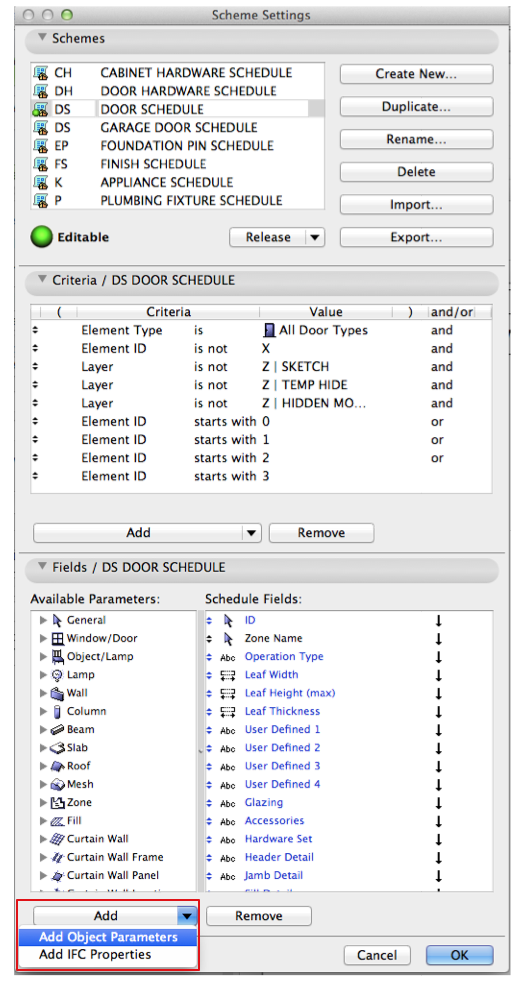
Take a quick look at the Schedule Scheme Settings in the upper right corner of the schedule window:

Screen Shot 2014-12-08 at 3.03.17 PM

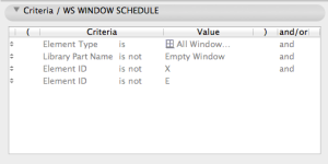
Then review the Schedule Criteria List in the scheme setting dialog box. These settings should be as minimal as needed to exclude what shouldn’t show up, but leave what should. Here is a great example of a list that works for a very complicated 4 story remodel project:

Screen Shot 2014-12-08 at 3.01.55 PM

If this is not the cause of the problem check your schedules view settings in the view map. Verify the layer combination is not excluding the walls that contain the door or windows. Also, verify the renovation status is not excluding the walls OR door/window units that the elements are defined as.

Screen Shot 2014-12-08 at 3.08.46 PM

Room Name or Home Story Will Not Schedule

This can be a trickier one to track down, since there are several reasons this happens. The first step I recommend is to review the window or door in plan view to assess its relationship with the schedule it should be scheduling to. There is a great shortcut for opening a selected schedule item in plan (or 3d) views.

Screen Shot 2014-12-08 at 1.37.40 PM

Once you have the opening selected in plan view select the zone it should be related to.

Screen Shot 2014-12-08 at 2.01.30 PMEverything looks ok and W01 should schedule… But it doesn’t! So look closer and you may find the zone is not running to the face of finish. Walls may have moved or the zone may have not been updated if linked to a zone boundary.

Screen Shot 2014-12-08 at 2.01.40 PMIf this all checks out and the window still will not list a room name check the window or door orientation. Remember that doors and windows have an outside and an inside, even if the whole element is technically not part of the building envelope. When you place a window or door you define the exterior via the little “sun” icon designating the prescribed exterior face of the wall.

Screen Shot 2014-12-08 at 2.08.48 PMIt may not be extremely clear which side is designated as exterior AFTER the unit is placed. But you can try “flipping” the orientation in the window/door selection settings. This redefines the exterior as opposite the installed orientation. It also flips the doors orientation in the wall; but a simple rotate and click will put the unit in the correct orientation while maintaining the newly assigned “exterior” face.

Screen Shot 2014-12-08 at 2.08.57 PMIf THIS doesn’t work we will need to dig deeper. Doors and windows do not associate to a distance greater than about 42″ above or below their story extents, as measured from their insertion point. The insertion point is the Header or Sill to _______ definition. If you insert using a typical header to home story setting, the insertion point is the header. If that header point is below its home story, regardless of the location and association of the zone to that story there is no practical method of listing a room name.

The solution to this is to set up stories appropriately. Half stories should have their own designated stories; this is an easier solution earlier in the project so discuss with the DDC & your model manager as soon as possible. We can show walls on multiple stories and have near perfect graphic control of what is shown as cut through using the floor plan cut plane settings. But that is a story for another post…

ADDITIONAL SCHEDULE CATEGORIES

Recently we were looking for parameters for a door schedule, but could not find them in the standard schedule scheme settings. If this happens they most likely will be located in the additional object parameters or the additional IFC properties.

Screen Shot 2014-09-29 at 8.58.58 AM

In the schedule Scheme Settings, click the down arrow to the right of the “Add” button (bottom left corner of the dialog box. This will give you a search box for the above mentioned additional parameters/properties. Virtually anything in an objects selection settings and IFC settings can be scheduled, you just need to find the object within the additional object parameters menu.

Screen Shot 2014-09-29 at 8.59.07 AM

A quick way to find these objects is to be sure to save the object as a favorite, or to use the appropriate favorites from the start. By using the favorites and having the correct favorites palette loaded you will be able to search for specific objects by the favorites list. Once you have the object selected it is a simple task to search through the schedule-able fields and find the category you want to add. If it shows up in an objects selection settings dialog box it should show up in the favorites Additional Object Parameters dialog box.

The parameters we were searching for were the “User Defined” elements of a Cadimage door. Using these, rather than the default “Custom Text”, we were able to have custom fields that tied directly to the door object rather than a global Custom Text. These User Defined list items were located in the favorites list under the Cadimage Door object.Screen Shot 2014-09-29 at 10.54.44 AM

SCHEDULING OBJECTS AND RELATIONSHIPS TO DRAWINGS

Leveraging the full power of BIM yields quick & coordinated results:

We have many great schedules at our finger tips, already created and waiting in our template.  Remember to leverage the use and creation of new schedules as documenting tools throughout the design and documenting process.  The images below show a sample foundation plan, possible 3d document associated with it.  These views were mocked up and saved in about 3 minutes using our template favorites.

Screen Shot 2014-09-11 at 11.50.29 AM Screen Shot 2014-09-11 at 11.54.14 AM

The question was posed today; how can I quickly reference these elevation markers in a list format with out the need to manage and update duplicate information?  The quick answer is with a schedule.  The schedule below will become available as part of our new template for those who need to list off any spot elevations on plan, elevation or 3d views.

Screen Shot 2014-09-11 at 11.47.33 AM Screen Shot 2014-09-11 at 11.46.32 AM

Where do I start when I want to schedule something?

I know I have discussed this before, both in person and on other blog posts, but like most good BIM workflow concepts things stem from the questions “what should be 2d and what should be 3d?”

The answer is always that if it shows up more than once it should probably be modeled.  In the above case, we have a simple spot elevation tag or datum.  This could easily be shown as a 2d symbol on the floor plan, but then the text is in constant need of babysitting and updating.  If we use the readily available 3d marker we can place it in the 3d view, review its location and contents in the 2d views. As a bonus we can scroll through a schedule list to confirm that all datum markers (and consequently the objects they are placed to) are in the right place.  Adding this little bit of additional information to your model helps ensure the level of precision is where it needs to be as well as opening up a huge range of documenting possibilities with little or no additional manual coordination.